How Does RF Absorber Work? Applications & Use Cases

How Does RF Absorber Work? Practical Applications and Use Cases
RF interference doesn't announce itself. It shows up in skewed test results, corrupted measurements, or signal degradation that takes hours to trace back to a reflection nobody accounted for. That's exactly why understanding how does RF absorber work matters – not just in theory, but in the day-to-day decisions that engineers make when designing test environments or protecting sensitive electronics.
The basic function of an RF absorber is straightforward: it takes incoming electromagnetic wave energy and turns it into heat instead of sending it back. A metal shield deflects energy. An absorber removes it from the equation. That's a fundamentally different approach, and the applications that depend on it are far more varied than most people assume.
What Happens Inside an RF Absorber?
Two separate physical mechanisms explain how RF absorbers do what they do – and which one dominates depends entirely on the material used.
Dielectric Loss vs. Magnetic Loss: What's the Difference?
Dielectric loss works through carbon-loaded foam. The carbon particles dispersed throughout the foam matrix resist the electric field component of an incoming wave. That resistance generates friction at the particle level, and friction produces heat. The wave keeps losing energy as it travels deeper into the foam – so the thicker the material, the more gets absorbed before anything can reflect.
Magnetic loss is a different story. Ferrite-based materials contain magnetic fillers – iron powder or sintered ferrite – that respond to the magnetic field component of the wave. As the field alternates, the magnetic domains inside the material rotate back and forth to follow it. That rotation costs energy, and that energy comes out as heat. Ferrite tiles work best at 30 MHz to 1 GHz, a range where carbon foam simply doesn't have enough loss per unit thickness to perform well.
Hybrid absorbers pull both mechanisms together – ferrite on the bottom, foam pyramids on top – for applications where neither material alone covers the required bandwidth.

The Three-Stage Absorption Process
Every time an RF wave contacts an absorber surface, the same sequence plays out:
- Incident phase – The wave hits the surface. Some of it reflects off immediately; the rest enters the material.
- Attenuation phase – Inside the absorber, the wave interacts with carbon particles or magnetic fillers. With each interaction, it loses a portion of its energy to heat.
- Dissipation phase – What little energy remains gets converted to low-level heat and released harmlessly. Nothing significant bounces back.
The third stage depends heavily on material quality and geometry. A low-grade absorber might attenuate a wave adequately but still leak enough residual reflection to throw off precision measurements – especially in antenna test chambers where even -25 dB of unwanted reflection is too much.
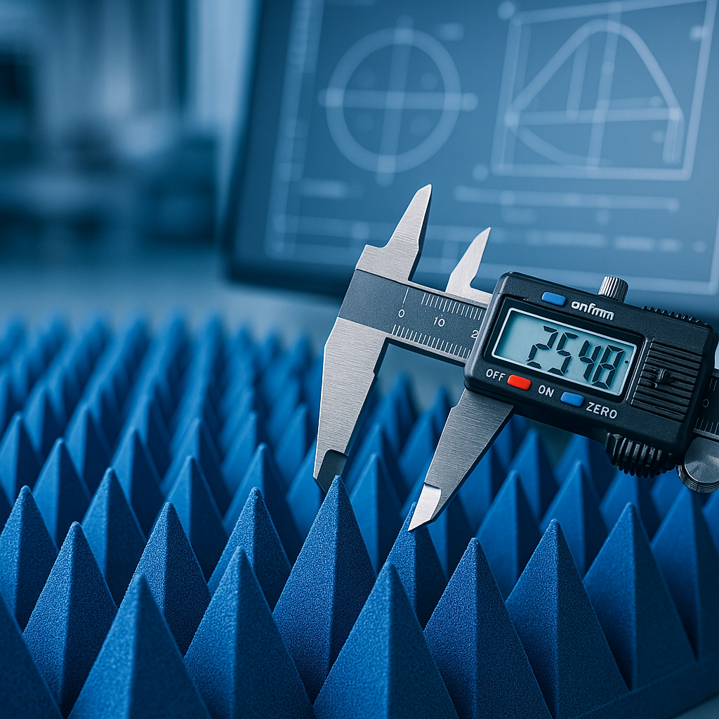
Why Pyramidal Geometry Outperforms Flat Panels
The pyramid shape solves a real problem: abrupt impedance mismatch at the surface. When a wave hits a flat panel, it encounters a sudden transition from free space to a lossy material. Some portion reflects at that boundary no matter what.
A tapered pyramid tip has electrical properties close to free space. The mismatch is minimal, so little reflects. The wave enters and works its way toward the thicker base, where loss density increases steadily until almost nothing is left to bounce back. This impedance tapering is why the pyramidal foam absorber design consistently outperforms flat alternatives.
Performance note: High-quality pyramidal foam achieves -40 dB to -60 dB reflectivity, compared to around -20 dB for standard flat foam panels – a difference that determines whether a chamber produces reliable data or not.
RF Absorber Types: A Practical Comparison
Picking the wrong absorber type is a common and costly mistake. The table below covers the main options across the parameters that matter most in practice:
| Absorber Type | Frequency Range | Primary Mechanism | Typical Form |
|---|---|---|---|
| Pyramidal Foam | 200 MHz – 40+ GHz | Dielectric (carbon) | Foam pyramids, wedges |
| Ferrite Tile | 30 MHz – 1 GHz | Magnetic (ferrite) | Rigid flat tiles |
| Hybrid (Ferrite + Foam) | 30 MHz – 40+ GHz | Mixed | Layered tile/pyramid combo |
| Elastomer Sheet | 500 MHz – 40 GHz | Magnetic (iron powder) | Flexible adhesive sheets |
Pyramidal foam handles the widest practical range for most test labs. Ferrite tiles are indispensable below 300 MHz. For broadband requirements, hybrid systems eliminate the need to build separate chamber sections for different frequency ranges.
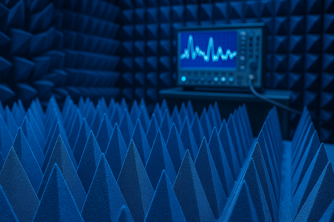
RF Absorber in Anechoic Chamber Applications
The RF absorber anechoic chamber is the most demanding environment any absorber material will face – not because peak performance is hard to achieve, but because consistency across the entire chamber surface is what actually determines measurement quality.
What Does an Anechoic Chamber Actually Simulate?
The goal is a room that behaves electromagnetically as though it has no walls. Test engineers working in RF absorber anechoic chamber setups rely on that simulation for:
- Antenna radiation pattern measurements free from wall-reflected interference
- EMC compliance validation against regulatory standards
- Device emission and immunity characterization across multiple frequency bands
- Radar cross-section (RCS) measurements in defense research
RF foam absorber tiles and pyramids line every interior surface. Even minor degradation – moisture penetrating foam cells, mechanical compression from foot traffic, or UV exposure over the years – shifts the absorption characteristics enough to introduce errors that are hard to catch because the reflections remain below obvious detection thresholds.
Anechoic chamber construction guidelines show how absorber selection shifts with application. A cellular antenna test chamber at 600 MHz to 6 GHz calls for different material choices than a mmWave radar chamber operating above 24 GHz.
Hybrid Absorbers for Wide-Spectrum Coverage
Below 200 MHz, standard pyramidal foam starts losing effectiveness. The material becomes too thin relative to the wavelength for adequate absorption depth. Ferrite tiles address this at the base layer, absorbing the low-frequency energy magnetically, while the foam pyramids mounted on top handle everything above that threshold. The combination extends usable coverage from 30 MHz to 40+ GHz in one installation – practical for labs that can't afford two separate chambers.

How to Choose the Right RF Absorber
Selecting the appropriate absorber depends on four factors worth evaluating before specifying any material:
- Frequency range – ferrite tiles for sub-300 MHz, pyramidal foam for mid-to-high frequencies, hybrids where broad coverage matters
- Required reflectivity – most professional anechoic chamber applications need -40 dB or better; research and defense work often demands -50 dB
- Installation constraints – limited chamber depth may require shorter pyramids with adjusted geometry; flexible sheet absorbers handle curved or irregular surfaces
- Environmental exposure – humid or outdoor conditions call for sealed-cell foam with weather-resistant coatings; standard open-cell foam degrades quickly when wet
Pro tip: Subpar absorption doesn't always show up as an obvious test failure. Often it produces results that look plausible but don't repeat – a sign that reflections are adding noise below the threshold of obvious detection.
Need pyramidal anechoic absorbers that consistently hit the reflectivity specs your application demands? Browse the full absorber product range at DB Absorber or contact the technical team to talk through chamber requirements, custom dimensions, and installation options. Accurate RF testing depends on the right material choice from the start.
Frequently Asked Questions
What is the difference between an RF absorber and an RF shield?
A shield reflects energy away. An absorber converts it to heat. Shields work well for blocking external interference from reaching a protected space; absorbers are needed when internal reflections within an enclosure or test chamber are the actual problem.
How does RF absorber work at very low frequencies?
Below 300 MHz, carbon foam loses effectiveness because the material thickness becomes too small relative to the wavelength. Ferrite tiles use magnetic loss instead of dielectric loss and perform well in this range. Hybrid designs stack ferrite and foam to cover both ends without sacrificing low-frequency performance.
What causes an RF foam absorber to degrade over time?
Moisture is the main culprit – water alters the foam's dielectric properties and shifts its absorption frequency. Mechanical compression from improper storage or foot traffic in walk-in chambers deforms the pyramid geometry and raises reflectivity. Sealed-cell foam with UV-stable coatings holds up significantly longer under real-world conditions.
What reflectivity does a professional anechoic chamber require?
Standard EMC and antenna test chambers specify -40 dB to -50 dB at the primary test frequency. Defense and high-precision facilities may require -50 dB or better. Flat foam panels at roughly -20 dB don't meet the threshold for serious test work.
Can RF absorbers be used outdoors?
Yes – with the right material. Standard carbon foam degrades quickly in humidity and sunlight. Weather-resistant versions with sealed-cell structures and protective surface coatings are built for outdoor antenna ranges and open-area test sites (OATS).