The Physics of Carbon Loaded Foam RF Absorbers

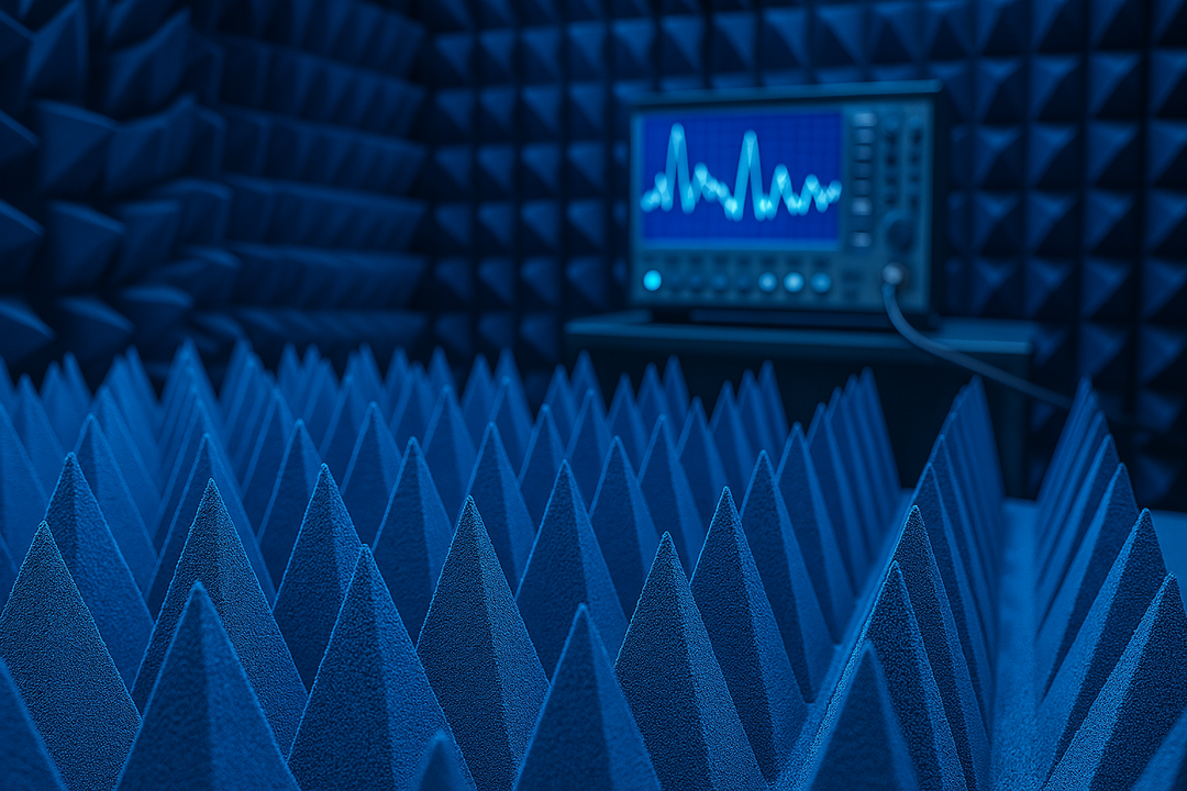
Why does one chamber lining absorb 99% of incoming radio waves while another lets stray signals bounce around for weeks, ruining test data? The answer sits in the material itself. Carbon loaded foam achieves this through a specific set of physical mechanisms – not magic, not marketing, just applied electromagnetics working the way it's supposed to.
Anyone specifying absorbers for an anechoic chamber, EMC lab, or antenna range eventually runs into the same question: what's actually happening inside this foam? Below is a breakdown of the mechanics, the research behind them, and what this means for choosing the right pyramidal absorber for a given application.
What Is Carbon Loaded Foam, Exactly?
Carbon loaded foam is an open-cell polyurethane structure infused with conductive carbon particles. On its own, polyurethane foam is nearly invisible to radio frequency energy – it lets waves pass straight through without much interaction.
Adding carbon changes that completely. The carbon particles form a conductive network throughout the foam, and that network is what gives the material its absorbing properties. Without carbon loading, foam is just packing material. With it, foam becomes a functional RF absorber.
Why Carbon Specifically?
Carbon is cheap, chemically stable, and electrically resistive – a combination that's hard to beat for this application. Other conductive fillers exist (carbon nanotubes, graphite flakes, even some metal particles), but standard carbon black remains the industry workhorse because it's consistent and easy to disperse evenly through a foam matrix.
A 2020 research on carbon fiber composites has shown that fiber length and dispersion quality directly affect dielectric performance, meaning how evenly and how finely the conductive material is distributed changes how well the finished product absorbs microwave energy. This is one reason manufacturing consistency matters more than it might seem at first glance.
How Does Carbon Loaded Foam Absorb Radio Waves?
Absorption happens through dielectric loss, a process where electromagnetic energy converts into heat as it moves through a resistive material. Here's the sequence, step by step:
- An electromagnetic wave enters the foam, and its oscillating electric field pushes free electrons through the carbon network.
- Carbon's natural electrical resistance turns that induced current into heat, following the formula P \= I²R – the same principle behind Joule heating in any resistive circuit.
- As the wave keeps traveling deeper into the material, its amplitude drops exponentially with each layer of carbon it crosses.
By the time a wave reaches the back of a properly designed absorber panel, there's little to nothing left of it. That's the entire goal of a carbon loaded foam RF absorber – not to block a signal, but to consume it.
The Problem With Just Blocking a Signal
A common misconception is that stopping a radio wave means reflecting it somewhere else. That's a mistake worth correcting early, because it leads to poor material choices.
A reflective surface doesn't destroy energy – it redirects it, often straight back toward the antenna or device being tested. In a measurement environment, that reflected energy shows up as interference, standing waves, or distorted readings. True absorption, not deflection, is what protects data integrity.
Why Are RF Absorbers Shaped Like Pyramids?
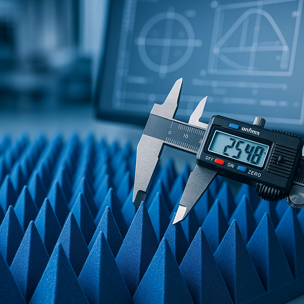
The pyramid shape exists to solve a specific engineering problem: getting the wave to enter the foam in the first place, rather than bouncing off the surface before absorption can even happen.
Free space has a characteristic impedance of approximately 377 ohms. If an absorbing material's surface impedance differs sharply from that value, most incoming energy reflects immediately, no matter how absorptive the material is on the inside.

Impedance Matching Through Gradual Geometry
Pyramidal foam solves this with a tapered profile. The tip of each pyramid is mostly air, so its impedance sits close to that of free space. As a wave travels toward the base, it meets progressively more foam and more carbon, which shifts the impedance gradually instead of abruptly.
This smooth transition is what allows the wave to enter with minimal reflection. It's the geometric half of the solution, working alongside the material's conductive properties.
Gradient Loading: Absorption That Increases With Depth
Beyond shape alone, the internal density of carbon loading typically increases from tip to base. That creates a gradient of absorption – light near the tip, heavier near the base – which traps the wave and strips away its remaining energy layer by layer.
Pyramid height and density aren't cosmetic choices. Taller, denser pyramids generally handle lower frequencies better, since longer wavelengths need more physical depth to be fully absorbed. Shorter pyramids work well at higher frequencies and take up less chamber space.
What Role Does Internal Scattering Play?
Open-cell foam isn't a solid block – it's closer to a sponge, full of irregular voids and internal surfaces. When a wave enters this structure, it doesn't travel in a straight line.
Instead, it scatters repeatedly off internal cell walls, which extends its actual travel distance far beyond the physical thickness of the panel. Every extra bounce gives the carbon network another opportunity to strip away energy. Studies on porous absorbing composites have documented this multi-scattering effect as a meaningful contributor to overall absorption performance, alongside dielectric loss itself.
Is There a Microscopic Component to Absorption?
Yes – and this part happens at a scale too small to observe directly. When carbon is loaded at the nanoscale, such as graphite flakes or carbon nanotubes, it introduces polarization effects inside the material.
Micro-dipoles form as the electromagnetic field oscillates, and because these dipoles can't shift instantaneously, there's a slight lag – a phase delay – between the field and the material's response. That lag itself dissipates energy as heat, adding a secondary absorption mechanism on top of standard conduction losses.
Comparing Absorber Geometries
Different chamber requirements call for different absorber profiles. The table below outlines how geometry choices generally affect performance:
| Absorber Type | Typical Frequency Range | Space Efficiency | Best Suited For |
|---|---|---|---|
| Tall pyramidal foam | Low frequency | Requires more depth | Full anechoic chambers, low-frequency EMC testing |
| Short pyramidal foam | High frequency | Compact | Space-limited setups, higher-frequency antenna testing |
| Wedge-style foam | Mid to high frequency | Moderate | Semi-anechoic environments |
Pro Tip: Matching pyramid height to the lowest frequency of interest is usually more important than matching it to the highest, since low frequencies demand more absorption depth.
Who Actually Needs This Kind of Absorber?
A handful of groups run into reflection problems often enough that carbon loaded foam becomes a standard part of their setup:
- EMC test labs working to meet compliance standards where even a small reflected signal can push results outside acceptable tolerances.
- Antenna developers who need clean, controlled conditions to characterize radiation patterns without interference.
- Chamber engineers building or renovating anechoic environments and needing broadband, dependable absorption without introducing new reflection points.
For each of these, absorber selection isn't a minor detail buried in a spec sheet. It affects whether test results can be trusted, repeated, and defended to a client or regulatory body.
Getting the Right Absorber for a Specific Setup
Pyramidal absorbers built from carbon loaded foam remain one of the most reliable tools for controlling reflections in test environments, precisely because their performance rests on well-documented physical mechanisms rather than guesswork.
For labs and engineers who need absorbers matched to a specific frequency range, chamber layout, or performance target, dbabsorber.com supplies pyramidal foam absorbers engineered around these exact principles. Reach out dB Absorber to discuss frequency requirements, available chamber space, or performance specifications, and get absorber recommendations grounded in physics that actually holds up under testing.
Frequently Asked Questions
Does carbon loaded foam work at all frequencies equally well?
No. Performance depends heavily on pyramid height and carbon density, with taller, denser structures needed for lower frequencies and shorter ones sufficient for higher frequencies.
How is carbon loaded foam different from standard packing foam?
Standard foam has no conductive network and barely interacts with radio waves. Carbon loading introduces the resistive pathways needed for actual absorption.
Can reflections from a poorly matched absorber really affect test results?
Yes. Reflected energy can create standing waves and distort readings, which is exactly what pyramidal geometry and proper impedance matching are designed to prevent.