How to Shield RF Signals in Anechoic Test Chambers

How to Shield RF Signals in Anechoic Test Chambers
Anechoic test chambers exist for one reason: to give engineers a space where electromagnetic signals behave exactly as expected – no stray interference, no wall reflections, no corrupted data. Building that environment is considerably harder than it sounds. Knowing how to shield RF signals properly means understanding the physics, choosing the right materials, and executing every detail without leaving gaps. One overlooked seam or an improperly filtered power line can compromise thousands of dollars' worth of test results.
The principles behind shielding RF signals are well-established. The challenge lies in applying them correctly across a wide frequency range – often from 14 kHz all the way up to 40 GHz – within a single chamber design.
The Foundation: Building a Faraday Cage That Actually Works
Every properly designed anechoic chamber begins with a complete metal enclosure – the Faraday cage. It's not a vague engineering concept; it's a very specific structural requirement. The cage needs to be a continuous conductive shell, and any break in that shell is a potential leak point for electromagnetic energy.
The two most common shielding materials used in chamber construction are:
- Galvanized steel panels (2mm) – the standard choice, offering durability, conductivity, and cost-efficiency for large enclosures
- Copper foil or copper sheeting – used when higher conductivity is needed, though significantly more expensive for full-wall coverage
How Panel Joints and Door Seals Determine Shielding Effectiveness
Panel joints are where many chambers fail. Bolting panels together isn't sufficient – conductive gaskets must be installed at every seam to maintain electrical continuity across the full structure.

RF doors follow the same logic. These are typically heavy, automatic sliding designs fitted with specialized compression seals. A door that warps slightly over time can create a gap wide enough to allow meaningful signal leakage, particularly at higher frequencies. Regular inspection of door seals is one of those maintenance tasks that gets overlooked until a chamber fails its attenuation retest.
Grounding: The Detail That Separates Good Chambers from Great Ones
Proper grounding is non-negotiable. The conductive floor must be bonded to the walls so the entire enclosure behaves as a single electrical ground reference.
Without this, voltage differentials can develop across the structure – effectively turning the chamber itself into a noise source. In high-performance chambers, shielding effectiveness can exceed 100 dB across frequencies from 14 kHz to 40 GHz. Reaching that figure requires grounding to be treated as a primary design requirement, not a finishing step.
Shielding RF Signals from the Inside Out: Absorbers and Hybrid Systems
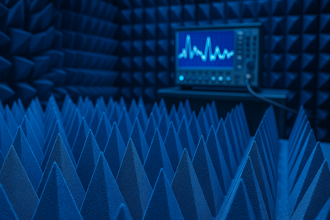
A Faraday cage stops external signals from entering – but it does nothing about reflections generated inside the chamber itself. When an RF signal bounces off a bare metal wall, it creates multipath interference that distorts antenna patterns and corrupts emission measurements.
This is where internal RF absorption becomes the second half of how to shield RF signals effectively.
Why Pyramidal Absorbers Are the Standard Interior Lining
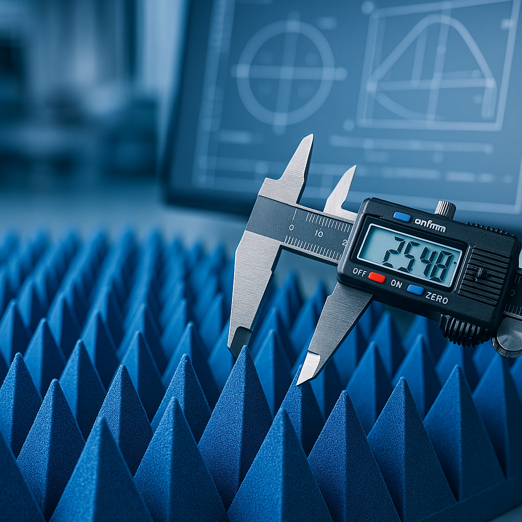
Carbon-loaded pyramidal foam absorbers line the walls, ceiling, and – in fully anechoic configurations – the floor. The pyramid shape is functional, not arbitrary. The tapered geometry creates a gradual impedance transition from the absorber tip, which presents near free-space impedance to incoming waves, down to the lossy carbon-loaded base. This gradient prevents sharp reflections and converts electromagnetic energy into heat across the material's depth.
- Pro tip: The lower the frequency you need to absorb, the taller the pyramid you need. Physical height must bear some meaningful relationship to the wavelength of the signal being attenuated.
Reflectivity performance by absorber size:
| Absorber Height | Effective From | Reflectivity at 300 MHz | Reflectivity at 40 GHz |
|---|---|---|---|
| 12 inches | \~300 MHz | −20 dB | −60 dB |
| 18 inches | \~200 MHz | Better than 12" | −60 dB+ |
| 36 inches | VHF range | Significantly improved | −60 dB+ |
dB Absorber's pyramidal product line covers cone heights from 2 inches to 36 inches. Each absorber is volumetrically loaded with carbon and fire retardants for consistent electromagnetic properties throughout the material – not just at the surface.
All quality absorbers should meet NRL 8000 fire retardancy standards. Chamber interiors are enclosed spaces with limited airflow, making this a safety baseline, not an optional spec upgrade.

The Low-Frequency Problem: What Happens Below 300 MHz?
Foam pyramids perform well above a few hundred MHz, but performance drops sharply at lower frequencies. Below roughly 200–300 MHz, the pyramid geometry becomes physically small relative to the wavelength, and absorption becomes unreliable.
Ferrite tiles solve this. These sintered ceramic materials attenuate magnetic fields and remain effective from around 30 MHz up to approximately 1–2 GHz. In hybrid configurations, ferrite tiles go on the chamber walls first, with foam pyramids mounted on top. The two materials divide the frequency spectrum between them:
- Ferrite tiles: Handle the low end (30 MHz – 1–2 GHz) through magnetic loss
- Pyramidal foam: Covers mid to high frequencies (\~200 MHz – 40 GHz+) through dielectric loss
- Hybrid systems: Provide continuous broadband coverage from 30 MHz to 40 GHz within a single lining assembly
This pairing is the most practical answer to broadband chamber performance without building separate chambers for different frequency bands.
Penetrations, Ventilation, and the Hidden Paths RF Takes
A structurally sound cage with quality absorbers still won't perform as expected if the support systems are ignored. Power lines, signal cables, and air ducts all create paths for RF energy to travel – and each one requires specific treatment. This is one of the most practically demanding parts of how to shield RF signals in any real installation.
Filtering Power Lines and Signal Cables
Every power line feeding the device under test (DUT) must pass through a high-performance EMI filter before entering the chamber. These filters suppress conducted interference while allowing the 50/60 Hz supply current through undisturbed.
The filter housing must be bonded to the chamber wall at the penetration point. A filter that's connected but not properly bonded can radiate at the connection itself – essentially creating a new leak point at the exact location designed to prevent one.
Signal cables need the same attention:
- Connectors should pass through bulkhead-mounted filtered adapters
- Coaxial penetrations must be shielded at the entry point
- Any unfiltered cable acts as a direct antenna, bridging the inside of the chamber to the outside environment
How Honeycomb Waveguide Vents Handle Airflow Without RF Leakage
Sealed chambers build up heat quickly during sustained or high-power testing. Standard perforated grilles allow RF to pass through freely – so proper chamber design uses honeycomb waveguide panels instead.
These panels use hexagonal metal cells sized so their cutoff frequency sits above the highest frequency of concern. RF signals attempting to propagate through the waveguide structure are attenuated exponentially. Airflow passes through; electromagnetic energy does not. It's an elegant mechanical solution to a problem that initially seems like it requires a compromise.

How to Validate Chamber Performance After Construction
Knowing how to shield RF signals is one thing. Verifying that the shielding works as specified is another.
Chamber performance is validated through attenuation testing per IEEE 299 or EN 50147-1, with measurements taken across the full specified frequency range. Most chambers are validated from 10 kHz to 18 GHz, with some extending to 40 GHz.
Acceptable reflectivity in the quiet zone – the calibrated measurement area at the chamber's center – typically falls between −20 dB and −30 dB at lower frequencies, improving substantially at higher frequencies. High-performance absorbers can push reflectivity down to −50 dB or better across upper frequency bands. For antenna testing applications, normalized site attenuation (NSA) must fall within ±4 dB of theoretical values to satisfy CISPR 16-1-4 validation requirements.
When a chamber fails attenuation testing, the most common culprits are:
- Door seals – warped or compressed seals that no longer make full contact
- Panel joints – gaskets that have shifted, degraded, or were never properly installed
- Cable penetrations – unfiltered or improperly bonded entries
- Recently added equipment – new fixtures or modifications that inadvertently broke the shielding continuity
Systematic inspection of these four areas resolves the majority of unexpected chamber failures.
Ready to Line or Upgrade Your Chamber?
Shielding RF signals inside an anechoic chamber comes down to material quality, construction precision, and closing every gap in the system – structural, electrical, and mechanical. The absorbers chosen for the interior lining directly determine how accurately the chamber performs across its rated frequency range.
dB Absorber's pyramidal RF absorbers are built from open-cell polyurethane foam volumetrically loaded with carbon and fire retardants, tested to NRL 8000 standards, and available in sizes from 2 inches to 36 inches. Whether the application is EMC compliance testing, antenna pattern measurement, or radar testing, there's a configuration that matches the chamber's requirements.
Frequently Asked Questions
What frequency range does a typical anechoic chamber need to cover?
Most EMC test chambers are specified from 10 kHz to 18 GHz. Chambers used for antenna testing or millimeter-wave applications are often extended to 40 GHz. The absorber selection must match this range – smaller pyramids handle the high end, ferrite tiles or hybrid systems handle the low end.
What is the difference between a fully anechoic chamber and a semi-anechoic chamber?
A fully anechoic chamber (FAC) has absorbers on all six surfaces, including the floor. A semi-anechoic chamber (SAC) uses a reflective metal ground plane instead of floor absorbers, simulating an open-air test site above a ground plane. SACs are standard for radiated emissions testing per CISPR and FCC procedures.
How do pyramidal absorber height and low-frequency performance relate?
Pyramid height must bear a meaningful relationship to the wavelength of the signal being absorbed. A 12-inch absorber becomes effective around 300 MHz. An 18-inch absorber extends coverage to 200 MHz. For measurements down into the VHF range, 36-inch pyramids are required – or a ferrite tile hybrid system is used to compensate.
What fire safety standards should RF absorbers meet?
Absorbers used in enclosed chamber environments should meet NRL 8000 fire retardancy requirements (Tests I, II, and III). Optional certifications include UL94 and DIN 4102-B2, which may be required depending on the facility's building code or customer specifications.
What causes a chamber to fail attenuation retesting after it initially passed?
The most common causes are door seal degradation, loosened panel gaskets, new cable penetrations that weren't properly filtered, and physical modifications to the chamber structure. Periodic inspection of seals and penetrations is the most effective preventive measure.