The Pro List of RF Components for 5G & 6G Environments

The Pro List of RF Components for 5G & 6G Environments
Most engineers can name the active components in an RF chain without hesitation – amplifiers, transceivers, mixers. But when test results don't match the simulation, the cause is rarely the component everyone was watching. It's usually what was ignored.
At 5G and 6G frequencies, the mmWave spectrum spans 30 GHz to 300 GHz and beyond. Wavelengths at these bands are short enough that minor physical imperfections in a test setup – a reflective wall, a poorly selected connector – can invalidate an entire measurement session. That's the environment this guide is built for.
Active RF Components: The Signal Chain Core
Active RF components draw power and directly process signals. Getting these right is non-negotiable for any 5G or 6G deployment or test platform.

Power Amplifiers and Low-Noise Amplifiers
Power amplifiers (PAs) boost transmitted signals to propagation-ready levels. Low-noise amplifiers (LNAs) handle the receive side, amplifying weak signals while adding minimal noise to the chain.
At mmWave frequencies, GaN-based PA designs lead the field. Compared to traditional silicon CMOS, GaN offers higher power density and wider bandwidth – advantages that become significant when the target bands stretch from 30 GHz to beyond 300 GHz. That said, high gain alone isn't the goal. High clean gain is.
At 30 GHz or 300 GHz, parasitic oscillations become a real problem. These are unwanted signals that bounce between the PA and nearby metallic surfaces, corrupting output and causing instability. In a deployed system, this degrades performance. In a test setup, it produces misleading data. Microwave foam absorbers placed around amplifiers are one of the most underused – and most effective – tools for suppressing this behavior before it propagates through the measurement.
Transceivers and Phase Shifters
Modern 5G transceiver ICs pack transmit and receive functionality into a single module, with phase shifters and attenuators integrated for beamforming control. Phased-array antennas depend entirely on precise phase alignment across every element. Even a 1-degree phase error at 28 GHz produces a measurable shift in beam direction – enough to matter in a calibrated test environment.
System-on-package (SoP) integration keeps parasitics low at high frequencies, but it concentrates heat in tight areas. Thermal drift in one element affects the whole module, which is why thermal management and EMI isolation need to be designed in, not patched after.
Passive RF/Microwave Components: Precision Without Power
Passive RF components don't need a power source, but they shape signal quality as much as anything active in the chain. At mmWave frequencies, the margin for error is narrow.

The most important passive RF microwave components in a 5G or 6G system include:
- Filters – Must isolate tightly packed frequency channels. Substrate-integrated waveguide (SIW) technology has become a leading solution for mmWave filter design, offering compact size with strong out-of-band rejection.
- Attenuators – Reduce signal power without distorting the waveform. Above 30 GHz, maintaining flat attenuation across a wide bandwidth is technically demanding; PCB substrate properties, connector quality, and mechanical tolerances all affect it.
- Couplers and power dividers – Directional couplers sample a portion of the signal path for measurement without disrupting the main line. In OTA test setups, these maintain accurate power references throughout the chain.
What Connector Format Should You Use Above 40 GHz?
Standard SMA connectors stop performing reliably well before 40 GHz. For 6G test environments and upper-band 5G work, 2.4 mm and 1.85 mm connector formats (K and V connectors) are the appropriate choice – supporting operation to 50 GHz and 67 GHz respectively, with some formats rated well above 100 GHz.
Mismatch at a connector junction creates reflections that travel back through the signal chain. This isn't a minor calibration nuisance – at millimeter-wave frequencies, those reflections can swamp the signal being measured. Transmission line selection follows the same logic: insertion loss scales sharply with frequency, and a microstrip trace that performs fine at 3.5 GHz may introduce unacceptable loss at 28 GHz.
The RF Component That Belongs on Every Checklist
Why do absorbers consistently get treated as optional when they affect the validity of every measurement made by the active and passive components around them?
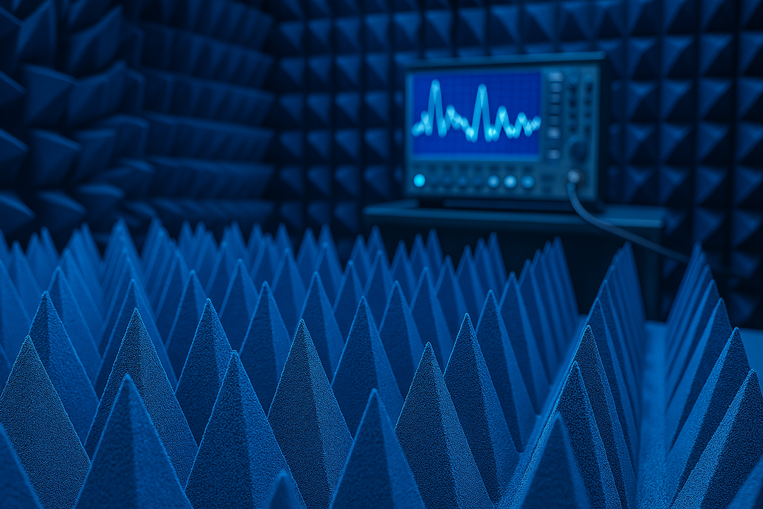
Cavity resonance is one of the most common sources of error in high-frequency test environments. RF energy reflecting off metallic enclosure walls or PCB ground planes creates standing waves that interfere with the device under test. At 5G and 6G wavelengths, even small reflective surfaces can corrupt the quiet zone of a test chamber – and a corrupted quiet zone means corrupted data.
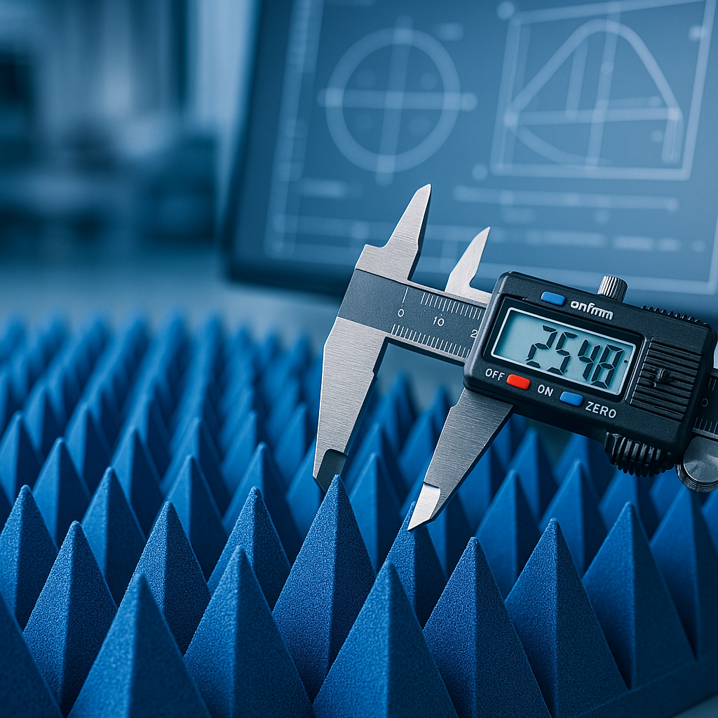
Pyramidal anechoic absorbers address this directly. The pyramidal geometry creates a graded impedance transition from free space to the absorber body, which minimizes surface reflections far more effectively than flat absorber material. DB Absorber's 12" pyramidal foam units are a standard solution in professional anechoic chambers for exactly this reason – the shape is functional, not decorative.

The market reflects this understanding. The global RF anechoic absorber market reached USD 1.12 billion in 2024, with a projected CAGR of 7.3% through 2033. Growth is driven by expanding 5G OTA testing infrastructure and the early stages of 6G development, both of which require reflection-controlled environments to produce trustworthy measurements.
How to Select RF Microwave Components for mmWave Environments
Getting the component stack right for 5G and 6G isn't just about maximum frequency rating. Four factors drive the selection decision at mmWave:
- Frequency range – FR1 (sub-6 GHz) and FR2 (mmWave, n257–n261) components are not interchangeable. 6G research is already targeting bands above 100 GHz, which requires a separate component tier entirely.
- Insertion loss budget – At mmWave, even 0.5 dB of unexpected loss matters. Every connector, line segment, and passive element adds to the total. Account for all of it.
- Thermal management – Integrated modules concentrate heat. Without adequate thermal paths, component drift introduces measurement error and shortens service life.
- Environmental isolation – A filter that meets spec on a benchtop may behave differently inside a metallic enclosure. Experimental mmWave absorber validation at 28 GHz, 33 GHz, and 38 GHz consistently shows that chamber conditions directly affect measurement fidelity. The absorber environment and the component environment are not separate problems.
Get the Absorber Specification Right Before Testing Starts
DB Absorber supplies pyramidal anechoic absorbers built for the frequency demands of modern 5G and 6G test environments. Whether the application is antenna characterization, EMC compliance, or OTA chamber construction, the absorber specification belongs in the design process – not as an afterthought.
Frequently Asked Questions
What are the main categories of RF components in a 5G system?
Active components – amplifiers, transceivers, phase shifters – process and generate signals. Passive RF microwave components – filters, attenuators, couplers, connectors – shape signal quality without external power. Environmental components, including anechoic absorbers, control the electromagnetic conditions in which all of the above operate.
Why do mmWave frequencies require different connectors?
At frequencies above 30 GHz, standard SMA connectors introduce significant insertion loss and reflection due to physical geometry. 2.4 mm and 1.85 mm formats are designed for the tighter mechanical tolerances mmWave signals require.
How does a pyramidal absorber improve test accuracy?
The pyramidal shape creates a gradual impedance transition between free space and the absorber body. This graded structure minimizes the surface reflection that flat materials cannot avoid – which is why pyramidal geometry is the standard in professionally built anechoic chambers.
When should absorbers be specified?
At the design stage, not after measurements come back wrong. Absorber placement around power amplifiers, antenna arrays, and chamber walls should be part of the initial test setup specification, treated with the same rigor as component selection.