Anechoic Chamber Quiet Zone Optimization: Maximizing Your Testing Area
Meta description: Learn how to optimize your anechoic chamber quiet zone for precise RF testing. Discover design strategies, material choices, and software tools for superior performance.
Anechoic Chamber Quiet Zone Optimization: Maximizing Your Testing Area
Radio frequency testing requires absolute precision, and that precision depends entirely on the anechoic chamber quiet zone. This carefully controlled space is where electromagnetic measurements happen without interference from unwanted reflections. Getting this zone right can make or break antenna development, radar system validation, and wireless device certification projects.
The quiet zone anechoic chamber represents a rectangular volume where electromagnetic waves bouncing off surfaces stay below specific thresholds. Picture it as a bubble of electromagnetic silence inside a larger controlled room. Engineers juggle multiple variables to create this zone—from room dimensions to wall materials. Building an ample space with absorbing materials isn't enough. The real goal is creating an environment where wave physics work in harmony with testing needs.
What Makes a Quiet Zone Actually Quiet?
The quality of an anechoic chamber quiet zone comes down to how electromagnetic waves behave inside the enclosed space. When a transmitting antenna sends signals, the receiving antenna should only pick up the direct path. But waves reflect off surfaces, creating secondary paths that mess with measurements.
Two main calculation methods help engineers figure out quiet zone chamber performance. The detailed approach accounts for every reflection in the test volume, tracking power gradients and multiple bounces. This method captures everything but needs serious computing power. The simplified method focuses on dominant factors—usually single-reflection waves from walls, ceiling, and floor. Four main paths matter most: two side walls, the ceiling, and the floor. This approach trades some accuracy for practical usability during initial design.
Getting the Physical Dimensions Right
Chamber size directly affects what's possible with the quiet zone. The relationship between chamber dimensions and test zone size follows electromagnetic principles, but it's not a simple one-to-one ratio. Doubling the chamber size doesn't automatically double the usable testing area.
Testing frequency range changes everything about size requirements:
- Low frequencies need more physical space between the antenna and the test object to achieve proper far-field conditions
- High frequencies allow compact arrangements but demand stricter field uniformity
- Millimeter-wave testing introduces unique challenges despite smaller wavelengths
- Broadband testing requires chambers that perform across wide frequency spans
Chamber shape goes beyond basic rectangular boxes. Some designs use tapered sections or offset antenna positioning to cut down on surface reflections. These tweaks can boost quiet zone anechoic chamber performance without expanding the physical footprint or buying pricier materials.
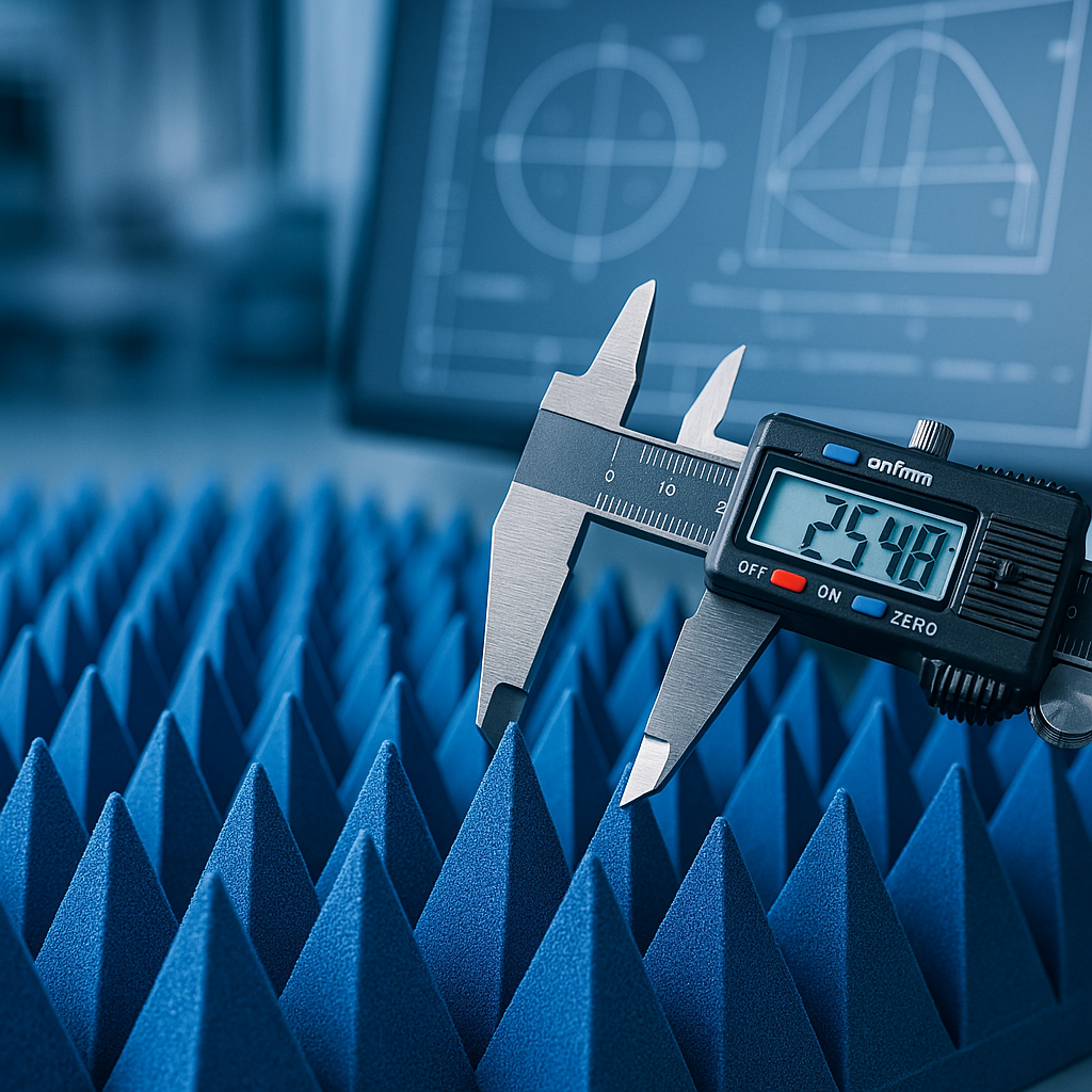
Choosing and Placing Absorber Materials
Materials lining the chamber walls determine how well electromagnetic energy gets absorbed instead of reflected. RF absorbers come in different types—pyramidal foam, ferrite tiles, hybrid designs—each performing differently across frequency ranges and angles.
Smart absorber placement can overcome geometric limitations. Engineers map reflection paths using time-domain analysis, spotting which surfaces cause the most trouble. Putting better absorbers in problem spots—thicker materials or specialized shapes—beats upgrading every surface uniformly.
The spots where walls meet floors and ceilings need extra attention. These junctions create reflection patterns that standard absorber layouts can't handle well. Custom-shaped absorbers in corner areas smooth out the electromagnetic environment across the test volume.
Using Software to Design Smarter
Software simulation has changed the game for anechoic chamber quiet zone design. Programs like Ansys HFSS let engineers model electromagnetic behavior before building anything. This ability moves the process away from guesswork toward predictable outcomes.
Simulation catches details that calculations miss. The way absorber materials, chamber geometry, and antenna patterns interact creates effects that simple models don't predict. Designers can test multiple configurations virtually and find the best solution. Fixing design problems in software costs a fraction of retrofitting a finished chamber.
These models also let engineers try unconventional ideas—testing weird absorber arrangements, evaluating different antenna positions, and checking how equipment fixtures affect performance. The virtual environment becomes a testing ground for experiments that would be impossible physically.
Compact Antenna Test Range Technology
For high-frequency work, especially millimeter-wave bands, CATR systems offer real advantages. These setups use a precisely shaped reflector to turn spherical waves from a feed antenna into plane waves inside the quiet zone chamber. This trick mimics far-field conditions in much smaller spaces.
CATR system quality depends on several factors. Reflector surface accuracy needs to stay within a fraction of a wavelength at peak frequency—a tough mechanical requirement. Edge treatments like serrated profiles minimize diffraction effects. Feed system design controls how evenly the reflector surface gets lit up, with array feeds offering more control than single elements.
Array feeds push the CATR capability further. Controlling multiple feed elements lets engineers shape the illumination pattern to reduce edge diffraction and reflections. This flexibility creates larger quiet zones for a given reflector size. The downside is added complexity and trickier calibration.
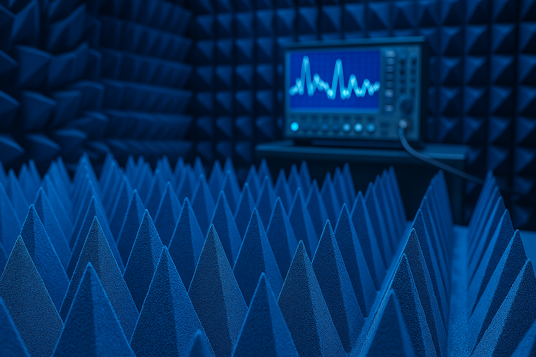
Checking That Everything Works
Building an optimized anechoic chamber quiet zone means nothing without proper testing. Site Voltage Standing Wave Ratio measurements use time-gating to isolate and measure reflected signals. These tests identify specific problems and verify compliance with industry standards.
Field uniformity checks examine amplitude and phase consistency across the test volume. Engineers measure at multiple points within the quiet zone anechoic chamber, mapping variations that could affect accuracy. Amplitude ripple specs typically range from ±0.5 dB to ±1.5 dB, depending on what's being tested.
Regular validation keeps chambers performing well over time. Absorber materials degrade from environmental exposure or damage. New equipment for specific tests might create fresh reflection paths. Periodic checks ensure the facility still meets design specs and catch degradation before it ruins test results.
Practical Ways to Improve Performance
Optimization doesn't always mean major upgrades. Sometimes small changes make significant differences:
- Adding extra absorbers in known problem areas
- Adjusting antenna positioning for better coverage
- Modifying test fixture designs to reduce reflections
- Upgrading absorbers in high-impact zones only
The idea of "good enough" matters in optimization work. Chasing tiny improvements in reflectivity can waste resources. Understanding actual measurement needs for specific test programs helps focus efforts where they provide real value instead of theoretical perfection.
Documentation of chamber characteristics enables smart decisions about testing approaches. When engineers know exactly how their quiet zone chamber behaves across frequencies and polarizations, they can design procedures that work within those limits or recognize when external facilities might be needed.
Looking Ahead
Wireless technology keeps advancing with 5G evolution and 6G research, so chamber technology must keep pace. Higher frequencies demand tighter tolerances and better absorber materials. Wider bandwidths need absorbers that perform consistently across broader ranges. Complex antenna arrays need bigger test zones.
Measurement speed matters more in commercial testing environments. Faster characterization methods could cut validation time significantly. Automated optimization might adjust test configurations on the fly to maintain peak performance across different scenarios.
Wrapping Up
The physics governing anechoic chamber quiet zone behavior stays constant, but our ability to work with these environments keeps getting better. Each advance in materials, computational methods, and measurement techniques opens new doors for creating superior testing spaces.
Facilities that adopt these improvements while maintaining strict validation deliver the accurate, reliable measurements that modern wireless technology demands. Getting the quiet zone right isn't just about following formulas—it's about understanding how all the pieces fit together to create a space where precise measurements can happen consistently.
Looking for high-quality RF absorbers? Browse our in-stock pyramidal absorbers — shipping from California in 1-2 business days.