EMI Shielding: 6 Proven Fixes for Lab Interference

EMI Shielding: 6 Proven Fixes for Lab Interference
Electromagnetic interference doesn't announce itself. One day the measurements look clean; the next, there's noise in the baseline, a sensor behaving strangely, or data that simply doesn't reproduce. Labs dealing with precision electronics, RF development, or sensitive analog signals know this frustration well – and the cause is almost always electromagnetic interference that wasn't properly managed from the start.
EMI shielding is the systematic answer to that problem. But "shielding" isn't one thing – it's a layered discipline that combines materials, grounding, layout, and filtering into a coherent defense against unwanted electromagnetic energy.
Why Lab Interference Is a Bigger Problem Than It Looks
Most labs accumulate equipment gradually. A switching power supply here, a new instrument there, a wireless device on the bench. Each addition changes the electromagnetic environment, and over time the interference floor rises to a point where it affects measurements.

According to IEC 61000 standards, electromagnetic compatibility (EMC) in laboratory environments requires both emissions control and immunity – meaning equipment must neither generate interference beyond defined limits nor be vulnerable to interference from outside. Most labs operate somewhere between compliant and chaotic, and the gap shows up in data quality.
The core issue comes down to two mechanisms:
- Conducted interference – noise traveling through wiring and power lines
- Radiated interference – electromagnetic energy propagating through space
Both require different solutions. Most real-world lab problems involve a combination of the two, which is why a single fix rarely resolves everything.
Fix 1: Conductive Enclosures – Faraday's Principle, Modern Application
A Faraday cage works because free charges in a conductor redistribute in response to an external electric field, canceling the field inside. Surround a sensitive circuit with a continuous conductive shell – aluminum, copper, or steel – and external electromagnetic fields stay outside.

For PCB-level protection, shielded cans soldered directly to the board serve the same function at a smaller scale. Conductive adhesive-backed foil handles irregular geometries where rigid cans won't fit.
Common enclosure materials and their strengths:
| Material | Best For | Notes |
|---|---|---|
| Copper | Broadband shielding | Highest conductivity, handles both E and H fields |
| Aluminum | Lightweight applications | Excellent conductivity, easy to machine |
| Steel / Mu-metal | Low-frequency magnetic fields | Higher permeability, absorbs rather than reflects |
- Pro tip: Even a well-made enclosure fails at its seams. Gaps as small as a fraction of the interference wavelength act as slot antennas. Seal them with conductive gaskets or adhesive foil before assuming the enclosure is doing its job.
Fix 2: Shielded Cables and Conductive Gaskets
Any break in a conductive enclosure – a cable entry, a ventilation slot, a connector port – is a potential source or entry point for electromagnetic interference. Cables are particularly problematic because they run between shielded areas and unshielded ones, acting as antennas in both directions.
Shielded twisted pair cable is the standard fix for analog signal lines. The twist reduces inductive coupling; the shield blocks radiated interference. The shield should be grounded at the quietest end of the signal path – grounding at both ends creates a ground loop, which often introduces more noise than the original problem.
Conductive gaskets are equally necessary at panel interfaces. Common gasket materials include:
- Beryllium copper fingerstock – high contact force, excellent conductivity, durable
- Wire mesh gaskets – good compression range, cost-effective for large seams
- Conductive elastomers – useful where environmental sealing is also required
Without proper gasket contact, the panel interface becomes a slot antenna. EMI interference shielding at the enclosure level is only as effective as the continuity of its conductive boundary.
Fix 3: Grounding – The Fix That Costs the Least and Gets Ignored the Most
Poor grounding causes more lab EMI problems than most engineers estimate. A shield that isn't properly bonded to ground isn't functioning as a shield – it's a floating conductor that can re-radiate the interference it was meant to stop.
The fix is a low-impedance ground connection: short, direct, with as little inductance as possible. For metal enclosures, this means filing away paint at bonding points before attaching ground straps. Painted surfaces are insulators. The metal-to-metal contact is what matters.
At the PCB level, solid copper ground planes reduce loop area throughout the board, providing consistent return paths that make EMI shielding materials perform as intended. Segmented or partial ground planes are a common design error that undermines shielding effectiveness regardless of what's placed on top.
Fix 4: Ferrite Cores – Absorption Rather Than Reflection
Conductive shields reflect electromagnetic energy. Ferrite materials do something different – they absorb it, converting high-frequency noise into a small amount of heat through magnetic loss mechanisms. This makes them particularly effective for common-mode noise on cables.

Clamping ferrite chokes onto power cables and data lines attenuates noise, especially on runs longer than approximately 0.5 meters. The key is matching the ferrite material to the frequency range:
- Manganese-zinc (MnZn) ferrites – effective below \~10 MHz
- Nickel-zinc (NiZn) ferrites – better performance from 10 MHz to several hundred MHz
Installing the wrong material for the frequency range produces no measurable improvement. Always cross-reference the manufacturer's impedance curves against the problem frequency before specifying a core.
Fix 5: EMI Filters on Power Lines
Power lines are one of the most reliable pathways for conducted interference. A switching power supply on the same circuit as a sensitive instrument pushes noise back through the building wiring, and that noise re-enters the instrument through its power input. Standard EMI filters – passive combinations of capacitors and inductors – are designed specifically to block these frequencies.
Capacitors shunt high-frequency noise to ground; inductors block it from passing through. Together, they form a low-pass filter that allows 50/60 Hz power through while attenuating interference at higher frequencies.
Installing line filters at the power entry point of critical instruments is one of the highest-ROI interventions in lab EMI management, particularly in environments where heavy machinery and precision measurement equipment share electrical infrastructure.
- Note: Line filters must be rated for the actual line voltage and current draw of the equipment. An undersized filter creates a safety hazard in addition to performing poorly.
Fix 6: Cable Routing – Layout Decisions That Change Everything
No amount of EMI shielding compensates for poor cable management. Power cables and signal cables running in parallel create inductive coupling – the changing magnetic field around a current-carrying conductor induces a voltage in any adjacent conductor. The induced voltage appears directly in the measurement signal.
The solutions are straightforward and require no additional components:
- Separate power and signal wiring – run them in different conduits or opposite sides of cable trays
- Maintain separation distance – even 15–20 cm of spacing between power and signal runs reduces coupling significantly
- Cross at 90 degrees – when cables must cross, perpendicular crossing minimizes the shared magnetic flux
- Keep cable runs as short as practical – longer cables have more surface area to act as receiving antennas
These layout principles cost nothing to implement during installation and are extremely difficult to retrofit after a lab is fully set up.
EMI Shielding Materials: What the Research Actually Shows
The science of EMI shielding materials has advanced considerably in recent years. Traditional metals remain the performance benchmark, but newer materials offer characteristics that rigid metal enclosures can't provide.
Established materials:
- Copper – shielding effectiveness above 100 dB across a broad frequency range; handles both electric and magnetic fields
- Aluminum – lighter than copper with conductivity around 61% of copper; preferred where weight matters
- Mu-metal – nickel-iron alloy with relative permeability up to 100,000; purpose-built for low-frequency magnetic shielding
Emerging EMI shielding materials include MXene-based composites (two-dimensional titanium carbide compounds), graphene foams, and conductive polymer composites. Research published in journals including Advanced Materials and ACS Nano has demonstrated shielding effectiveness values above 50 dB for MXene films at thicknesses below 1 mm – a performance level that traditional metal foils require far greater thickness to achieve.
For flexible or wearable applications, these advanced EMI shielding materials represent a genuine functional advance. For most bench-top lab applications, copper and aluminum enclosures remain the practical choice.
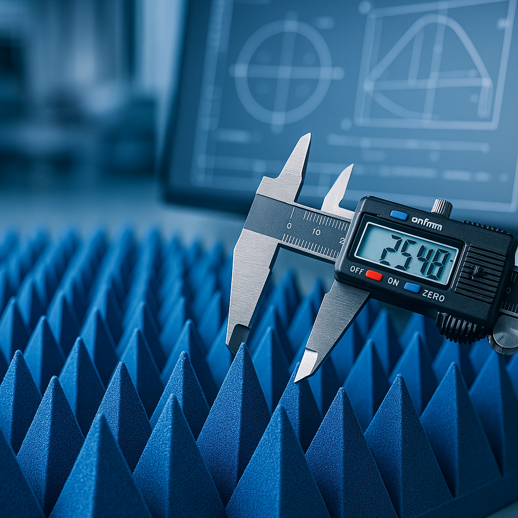
Where Pyramidal Anechoic Absorbers Fit In
Conductive EMI shielding keeps external interference out of a space. But what about the interference generated within a test environment by reflections? This is a separate problem – and one that conductive shielding alone cannot solve.

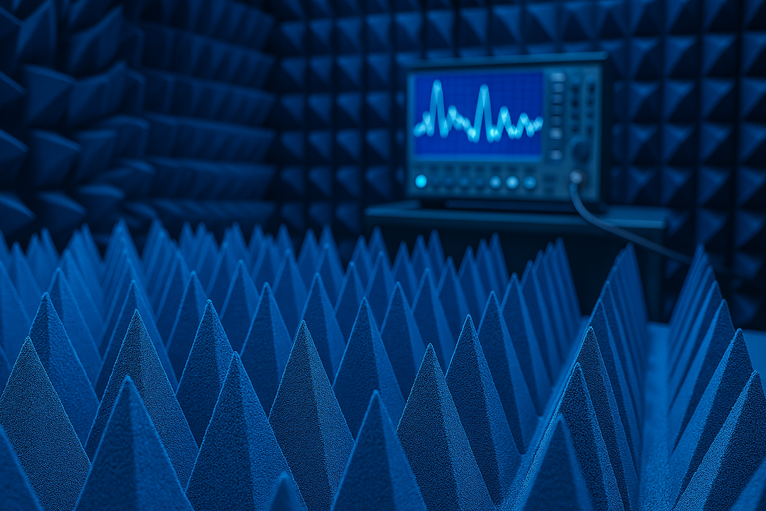
When measuring antenna patterns, conducting RF pre-compliance testing, or characterizing wireless devices, reflected electromagnetic energy from the walls of the test space contaminates the measurement. The antenna under test receives both the direct signal and multiple reflected versions of it, and the result is corrupted data that no amount of post-processing can fully correct.
Pyramidal anechoic absorbers address this by lining the test chamber walls with a material that absorbs incident electromagnetic waves rather than reflecting them. The pyramid geometry works by presenting a gradually increasing impedance to the incoming wave – a tapered transition that minimizes the surface reflection that a flat panel would produce. This is grounded in transmission line theory: abrupt impedance discontinuities cause reflections; gradual transitions do not.
For labs conducting any kind of RF measurement work, combining proper conductive EMI shielding at the room boundary with pyramidal absorbers on the interior walls is the complete, technically defensible solution. The shielding provides isolation from external sources; the absorbers create the clean internal environment that accurate RF measurement requires.
Explore the full range of absorber solutions – and build the measurement environment that precision work actually requires.
Frequently Asked Questions
What is the most effective material for EMI shielding in a lab?
Copper offers the highest shielding effectiveness across the broadest frequency range. For low-frequency magnetic fields specifically, mu-metal or other high-permeability steel alloys outperform copper.
How does EMI shielding differ from noise filtering?
Shielding prevents electromagnetic energy from entering or leaving a space through radiation. Filtering addresses conducted noise traveling through wiring. Effective lab protection requires both.
Do anechoic absorbers replace conductive shielding?
No – they serve different functions. Conductive shielding isolates the space from external electromagnetic sources. Absorbers control reflections within the shielded space. They work together, not as alternatives.
What is a realistic shielding effectiveness target for a lab enclosure?
MIL-STD-285 and IEEE 299 are standard test methods for measuring shielding effectiveness. General-purpose lab enclosures typically target 40–80 dB; high-performance RF chambers often exceed 100 dB.
Is EMI interference shielding regulated?
Yes. EMC regulations vary by region – FCC Part 15 in the United States, CE marking under CISPR standards in Europe – but all require that electronic equipment meet both emissions and immunity requirements.