Radiated Emission Test Fundamentals: Pre-Compliance Testing in Your Own Lab
Meta description: Learn how to conduct radiated emission pre-compliance testing in your own lab. Save time and money by identifying electromagnetic compatibility issues early.
Radiated Emission Test Fundamentals: Pre-Compliance Testing in Your Own Lab
Third-party test labs charge thousands of dollars per day, and scheduling appointments often means waiting weeks. When a product fails testing, the cycle repeats—more waiting, more money spent, and project deadlines slipping further away. Pre-compliance testing offers a practical solution by catching electromagnetic compatibility problems before formal qualification begins.
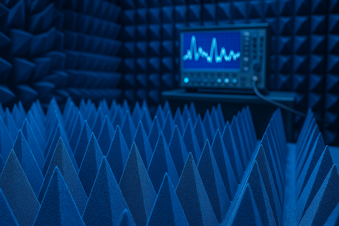
Commercial EMC facilities operate 10-meter semi-anechoic chambers costing over two million dollars. These specialized rooms feature complete RF shielding and walls lined with expensive absorber materials. However, companies can achieve surprisingly accurate results using modest equipment and available workspace. The secret lies in understanding which aspects of formal EMC radiated emissions testing truly matter and what can be reasonably approximated.
Building Your Radiated Emissions Testing Arsenal
The Heart of the System: Analyzers and Receivers
A quality spectrum analyzer forms the foundation of any radiated emission test setup. Most commercial and industrial products require measurements from 30 MHz to at least 1 GHz, though many current standards push testing through 6 GHz. Military applications may demand coverage up to 18 GHz, depending on product characteristics.
Modern benchtop analyzers from manufacturers like Rigol, Siglent, and Rohde & Schwarz deliver excellent performance without breaking budgets. The analyzer needs adequate sensitivity—typically a displayed average noise level better than -130 dBm. Entry-level models sometimes struggle with sensitivity, particularly at higher frequencies. A quality broadband RF preamplifier with 20-30 dB gain can bridge this gap and dramatically improve measurement capability.
Choosing the Right Antenna
Antenna selection significantly impacts whether pre-compliance results will accurately predict formal radiated emission test outcomes. Full-sized calibrated EMI antennas provide the best sensitivity and most accurate measurements, though they often measure a meter or more in length.
Key antenna considerations:
- Biconical dipoles work best for 30-300 MHz
- Log-periodic arrays cover 200 MHz to several gigahertz
- Each antenna includes calibration files for converting signal levels to field strength
- Storage space requirements increase with antenna size
Physically smaller antennas offer convenience but sacrifice sensitivity, especially at lower frequencies. Compact designs like the Tekbox TBMA1 work reasonably well at 1-3 meter test distances but lack the reach needed for 10-meter measurements below 300 MHz. Active antennas with built-in preamplifiers split the difference, fitting into small cases while delivering performance closer to full-sized models.
What Else Goes Into Your Kit
Beyond the analyzer and antenna, several items complete a functional setup:
Equipment
Purpose
Key Features
Tripod
Stable antenna positioning
Heavy-duty design for large antennas
Coaxial cables
Connect antenna to analyzer
Low-loss type like LMR-400
6 dB attenuator
Stabilize impedance match
Placed at antenna connection point
Ferrite chokes
Prevent cable interference
Clip-on style for easy application
Quality coaxial cables matter more than most engineers realize. Cable losses increase with frequency and can mask actual emission levels if not properly accounted for. Shorter cable runs minimize signal degradation, while low-loss cables preserve measurement accuracy across the frequency range.
Setting Up Your Test Space
Understanding Distance Requirements
Radiated emission test distance directly relates to the transition between near-field and far-field regions around radiating sources. In the near field, electromagnetic fields behave unpredictably with rapid strength changes based on position. Far-field measurements show more consistent behavior, with field strength decreasing proportionally to distance.
The far field begins at approximately one-sixth of a wavelength from the emission source. At 30 MHz, this translates to roughly 1.6 meters, while at 1 GHz, the far field starts at just 5 centimeters. Commercial standards typically specify either 3-meter or 10-meter test distances depending on product size. Military standards frequently use 1-meter spacing with fixed antenna heights.
Making the Most of Available Space
Conference rooms work surprisingly well for 3-meter radiated emission test setups. They offer adequate space while keeping everything close to troubleshooting tools and out of the weather. Walls, furniture, and other objects introduce reflections that wouldn't exist in anechoic chambers, but these effects usually remain minor compared to actual emission levels.
Practical test locations:
- Conference rooms (most popular for 3-meter setups)
- Office cubicles (antenna may extend into hallways)
- Parking lots or outdoor areas (weather dependent)
- Basements (naturally shielded from ambient signals)
Some companies use parking lots, taking advantage of concrete ground planes that mimic formal test facilities. This approach works well in good weather, though ambient RF signals from broadcast stations and mobile communications require consideration. Testing early morning or late evening can reduce ambient interference.
Getting Accurate Measurements
Polarization and Height Matter
Every radiated emission test requires checking both horizontal and vertical antenna polarizations since emission sources may radiate preferentially in one orientation. Rotating the antenna 90 degrees between measurements reveals which polarization captures maximum field strength. Some emissions show little difference, while others might vary by 20 dB or more.
Antenna height scanning represents another important technique. Standards typically specify antenna heights ranging from 1 to 4 meters for commercial testing. Varying antenna height while observing signal strength reveals the height that captures maximum emissions at each frequency. Pre-compliance testing can simplify this by testing at just two or three heights—perhaps 1 meter, 2 meters, and 3 meters.
Smart Scanning Strategies
Start with a broad frequency scan covering the entire required range using a relatively wide resolution bandwidth to quickly identify potential problem frequencies. Most products show emissions at the fundamental clock frequency plus harmonics extending through the spectrum. Switching power supplies generate distinctive comb patterns on spectrum displays.
Once problem frequencies are identified, zoom in with a narrower resolution bandwidth to see fine detail and accurately measure peak levels. Set the analyzer's detector mode to match applicable standards—usually quasi-peak for commercial testing below 1 GHz, peak detection above 1 GHz.
Near-Field vs Far-Field: What's the Connection?
Near-field probes excel at pinpointing emission sources on circuit boards and finding shielding gaps. However, the relationship between near-field signal strength and actual radiated emissions remains complex. A 10 dB reduction in near-field emissions rarely translates directly to a 10 dB drop in far-field measurements.
Not everything showing strong near-field emissions radiates efficiently in the far field. A short trace measuring 2 inches might show significant near-field emissions but prove too electrically short to radiate effectively. Conversely, a 6-foot cable carrying common-mode current operates as an efficient antenna and will definitely appear in far-field radiated emissions testing.
The practical approach involves using near-field probes for troubleshooting, then validating fixes with far-field measurements using a properly positioned antenna. Features measuring less than 1/20 wavelength at the frequency of concern probably won't radiate efficiently, while anything approaching 1/4 wavelength or longer deserves serious attention.
Making Sense of Your Results
Reading the Limit Lines
EMC standards define maximum allowable field strengths at specific frequencies and test distances. Converting measured signal levels into field strength requires accounting for antenna factor, cable losses, and any preamplifier gain. Most radiated emissions test equipment includes software that handles these calculations automatically.
Plot both measured emissions and applicable limit lines on the same graph. This visualization immediately reveals how much margin exists at each frequency or where failures occur. A margin of 6 dB or more provides good confidence that products will pass formal testing. Measurements within 3 dB of limits warrant concern and suggest finding emission sources or conducting formal pre-scans at accredited labs.
Adjusting for Setup Differences
Pre-compliance measurements in unshielded environments require interpretation to predict formal test outcomes accurately. Testing at 1 meter when standards require 3 meters means applying a distance correction factor—approximately 9.5 dB for three-times distance increases.
Ambient signals in radiated emission test environments will appear on the spectra along with product emissions. Learning to distinguish between them takes practice. Ambient broadcast stations show as continuous signals, remaining constant regardless of product operation. Product emissions usually appear as harmonic families with consistent frequency spacing and should change significantly when products are powered off.
Tracking Down Emission Sources
Cables: The Usual Suspects
Cables represent the most common radiated emission sources, particularly below 300 MHz. Common-mode currents flowing on cable shields or multi-conductor cables radiate efficiently because cables typically run for many wavelengths at lower frequencies. A current probe placed around cable bundles quickly reveals the presence and magnitude of these currents.
Effective cable fixes:
- Ferrite clamps near enclosure exit points
- Additional filtering at the connector pins
- 360-degree shield bonding instead of pigtail grounds
- Improved grounding practices
Testing each potential fix while monitoring emission levels allows rapid iteration toward solutions. This hands-on approach builds understanding faster than theoretical analysis alone.
When Enclosures Leak
Gaps, seams, and apertures in product enclosures allow electromagnetic energy to escape from internal sources. Shielding effectiveness depends heavily on the longest dimension of any opening relative to wavelength. Openings shorter than 1/20 wavelength at the highest frequency typically provide at least 20 dB of shielding.
Finding specific problematic seams requires systematic testing. A small near-field probe scanned around enclosures while monitoring analyzers at frequencies of concern, which will show increased signal strength near problem openings. Temporary fixes using conductive tape validate that sealing particular seams solves problems before committing to permanent design changes.
Making Testing Part of Your Process
Establishing regular pre-compliance testing throughout product development catches problems when fixes cost less and cause minimal schedule impact. Testing at the prototype stage identifies fundamental issues requiring circuit changes. Re-testing after each design iteration confirms improvements and reveals any new problems introduced by changes.
Document test setups, procedures, and results to create institutional knowledge that survives personnel changes. Include photos of radiated emission test arrangements, equipment settings, and measurement procedures. Over time, experience correlating pre-compliance results with formal test outcomes allows increasingly accurate predictions.
The investment in radiated emissions test equipment pays dividends through reduced test lab expenses, shorter development cycles, and fewer compliance surprises. Starting with basic equipment provides immediate value, while adding capabilities increases effectiveness over time. Most importantly, hands-on experience builds intuition about electromagnetic compatibility that proves invaluable throughout engineering careers.
Final Thoughts
Pre-compliance testing transforms EMC from a late-stage surprise into a manageable development activity. With modest investment in equipment and workspace, engineering teams gain the ability to identify and resolve emission problems before formal qualification. The result: fewer failed tests, lower costs, and products that meet regulatory requirements on the first attempt.
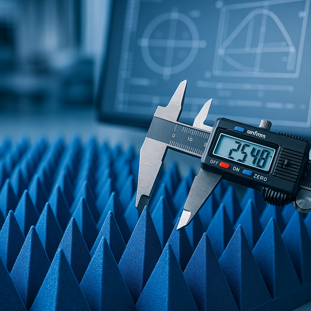
Looking for high-quality RF absorbers? Browse our in-stock pyramidal absorbers — shipping from California in 1-2 business days.