7 RF Testing Tools for Measuring Shielding Effectiveness

7 Essential Tools for Testing RF Shielding Effectiveness in the Field
Field testing RF shielding is one of those tasks where the wrong equipment doesn't just produce bad results – it produces confidently wrong results. Whether an engineer is verifying a Faraday cage at a medical facility or checking a shielded room after a structural renovation, the RF testing tools on hand determine how much trust can be placed in the final numbers.
The standard most commonly referenced for this kind of work is IEEE 299, which covers shielding effectiveness (SE) measurements across frequencies from 9 kHz to 18 GHz – with extensions possible up to 100 GHz. A well-executed RF shielding effectiveness test compares signal strength outside an enclosure against signal strength inside it. The difference, expressed in decibels, is the attenuation value. The higher that number, the more effective the shield.
Below are the seven RF testing tools that make a field test credible, repeatable, and defensible in a compliance context.
The 7 RF Testing Tools Every Field Engineer Should Know
1. Handheld Spectrum Analyzer
A portable spectrum analyzer is the receiving core of any RF shielding effectiveness test conducted outside a laboratory. Instruments like the Keysight FieldFox series or the SAF Tehnika Spectrum Compact are built for exactly this scenario – battery-powered, compact, and capable of measuring signal levels across a wide frequency range.

The analyzer sits inside the shielded enclosure and measures the output signal level (Pout). Without a calibrated, high-sensitivity receiver, even a well-planned RF testing tools setup will fall short on dynamic range. And insufficient dynamic range is one of the most common causes of unreliable shielding data in field conditions.
2. Portable RF Signal Generator
On the transmit side, a battery-powered RF signal generator produces a known continuous wave (CW) signal at a defined frequency and power level. Models like the Keysight N9310A or compact USB-controlled sources are well-suited for field use.
The generator feeds the transmitting antenna placed outside the enclosure, creating the reference signal (Pin) that the receiving setup will compare against the measured interior level.
Pro Tip: The generator's output must stay stable throughout the entire measurement. Any drift in signal level corrupts the attenuation calculation – frequency stability isn't just a specification preference, it's a test integrity requirement.

3. Calibrated Transmitting and Receiving Antennas
No two test scenarios are identical. Antenna selection is one of the more consequential parts of RF shielded test equipment planning, and it's directly tied to the frequency range being evaluated.
Antenna types by frequency range:
- Biconical or dipole antennas – suited to 30 MHz through 1 GHz for radiated field testing
- Horn antennas – the standard choice from 1 GHz up to 18 GHz and beyond
- Loop antennas – used for magnetic field (H-field) testing in the 1 kHz to 30 MHz range
Per IEEE 299, each antenna must be positioned approximately 30 centimeters from the enclosure surface, aligned tip-to-tip or edge-to-edge for maximum transmission efficiency. Misalignment artificially inflates the apparent attenuation – exactly the kind of false comfort that leads to compliance failures down the line.
4. Near-Field Probes (E-Field and H-Field)
Near-field probes are the diagnostic layer of a proper RF shielding effectiveness test. Where spectrum analyzers and antennas tell engineers whether an enclosure passes or fails overall, probes reveal where it's leaking – and that's often the more actionable result.

These small handheld probes connect directly to a spectrum analyzer and scan localized areas: door seams, cable penetrations, ventilation cutouts, and any point where shielding continuity might be interrupted. A door hinge that has lost conductive gasket contact, for example, may not significantly impact the overall SE measurement – but it still represents a genuine vulnerability. Near-field probes catch those details before they become problems.
5. High-Frequency, Low-Loss Coaxial Cables
Cable selection rarely gets the attention it deserves in field testing discussions. Long or low-quality cables introduce attenuation that quietly reduces dynamic range – meaning the measurement system can no longer detect the full attenuation depth the enclosure actually provides.

What to look for in field test cables:
- Low insertion loss across the full frequency range of interest
- Flexible construction for maneuvering inside enclosures (e.g., LMR-400UF)
- Documented length specifications – too long adds attenuation, too short limits reach
A cable that adds 3 dB of unaccounted loss effectively blinds the test at depth. This is precisely why a thorough test plan documents cable lengths and loss figures before a single measurement is taken.
6. Calibrated RF Attenuators
When a high-power transmit signal is used to achieve adequate dynamic range, the receiving spectrum analyzer needs protection from saturation. Calibrated RF attenuators step down signal levels at the analyzer input while maintaining a known, documented insertion loss.

Per IEEE 299 guidance, the dynamic range of the full test setup – calculated as the difference between the maximum and minimum measurable signals – must exceed the target SE value by at least 6 dB. Attenuators help maintain that margin while keeping measurements within the linear operating range of the instrument.
7. Portable RF Shielded Enclosure (Faraday Box)
When testing smaller devices in environments already saturated with ambient RF energy, a compact box creates the controlled conditions that make baseline measurements meaningful. Outdoor sites, active industrial floors, and busy office buildings can all produce background noise levels that overwhelm the signal of interest.
A portable shielded enclosure eliminates that ambient variable. It also serves as a useful verification environment for the RF testing tools themselves before a full test begins – confirming that the measurement chain is clean before enclosure walls enter the picture.

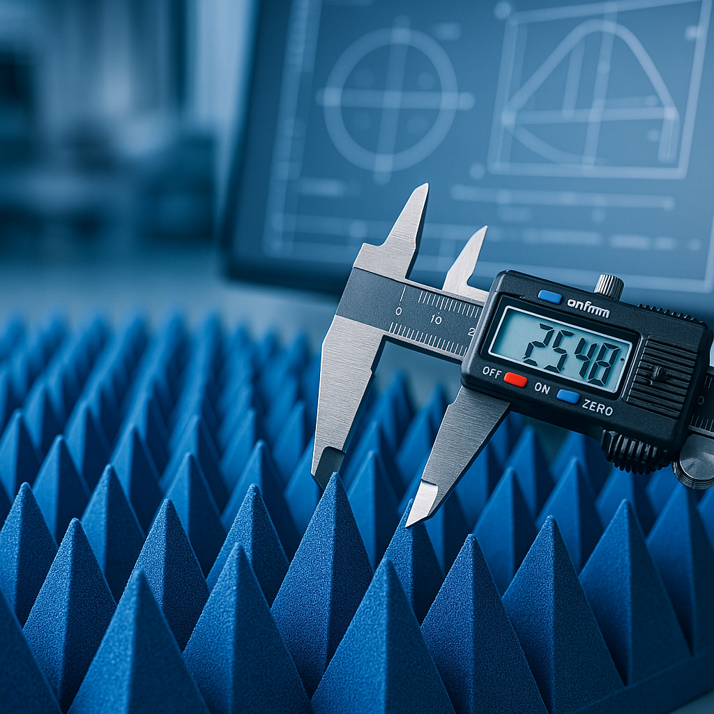
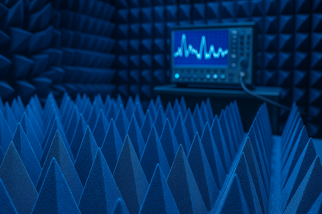
The Role of Anechoic Absorbers in Measurement Accuracy
There's a variable that doesn't always make it into standard RF testing tools checklists: multipath reflections. Inside a shielded enclosure, RF energy bounces off walls, floors, ceilings, and equipment. Those reflections interfere with direct-path measurements in ways that can meaningfully distort results – particularly at frequencies above 1 GHz.
Pyramidal anechoic absorbers address this directly. Placed on interior surfaces, they convert reflected RF energy into heat through absorption rather than re-radiation. The pyramid geometry is functional, not decorative – each tapered point creates a gradual impedance transition that prevents the abrupt surface reflection that flat conductive materials produce.
How Pyramidal Absorbers Improve Test Conditions
For any RF shielding effectiveness test that requires isolating direct-path transmission from multipath interference, absorbers shift results from approximately right to actually right. A measurement that includes uncorrected reflected energy gives a distorted picture of the enclosure's true attenuation performance.
DB Absorber's pyramidal anechoic absorbers are designed for demanding measurement environments, providing reliable broadband absorption without requiring permanent installation – which matters a great deal in field conditions.
Matching Absorber Size to Test Frequency
Absorber performance is directly tied to physical geometry. Here's the practical rule:
- Larger pyramids → effective absorption at lower frequencies (longer wavelengths)
- Smaller pyramids → sufficient for higher frequencies where wavelengths are short
- Broadband tests → always size to the lowest frequency of interest in the test plan
When an RF shielding effectiveness test spans a wide range – say, 100 MHz to 10 GHz – the absorber geometry should be matched to the lower boundary of that range.
What Does a Reference Measurement Establish?
The reference measurement is the baseline against which all attenuation values are calculated. It's taken with transmitting and receiving antennas separated by 60 centimeters in open space – no enclosure between them. This records the maximum signal level (Pin).
A separate measurement with only the receiver active records the noise floor. A 6 dB safety margin is added to that floor value. The span between the maximum signal and the adjusted noise floor is the dynamic range. That range must exceed the target SE value before any enclosure testing begins.
Once the dynamic range is confirmed, the receiving antenna moves inside the enclosure. Measurements proceed at defined test points across the required frequency range.
Standard test points per IEEE 299 include:
- Walls (all faces)
- Floor and ceiling
- Corners and edges
- Door frames and hinges
- Cable bulkheads and penetrations
- Ventilation panels
The shielding effectiveness at each point is then calculated using:
SE (dB) \= 10 × log₁₀ (Pin / Pout)
What SE Values Are Considered Acceptable?
Acceptable SE thresholds depend on frequency and application. Based on IEEE 299 and established industry benchmarks:
| Frequency Range | Minimum SE (High-Performance Shielding) |
|---|---|
| Up to 10 MHz | 100 dB |
| 10 MHz – 1 GHz | 80 dB |
| Above 1 GHz | 60 dB |
Source: MPB Electronic – IEEE 299 Standard Overview
These figures reflect real-world signal environments. MRI rooms, for example, typically require 90–100 dB at the scanner's operating frequency. EMC test chambers used for MIL-STD-461 compliance testing often require 100 dB or more.
Common Measurement Errors and How to Prevent Them
| Error Type | Root Cause | Prevention |
|---|---|---|
| Insufficient dynamic range | Low-gain antennas, no amplification | Add preamp; verify DR before starting |
| Antenna misalignment | Physical disturbance during test | Double-check alignment; keep personnel clear |
| Cable-induced attenuation | Low-quality or overly long cables | Use calibrated, low-loss cables; document lengths |
| Reflected path interference | No absorbers in the test setup | Add pyramidal absorbers on reflective surfaces |
| Frequency mismatch | Transmitter and receiver on different settings | Verify frequency alignment at each test point |
These five errors account for the majority of invalid results in practical field testing. Most are preventable with a disciplined pre-test checklist and the right RF shielded test equipment – including absorbers, which are still underused in field settings despite having a measurable impact on data quality.
Ready to Improve Your RF Test Environment?
The RF testing tools covered here form the measurement backbone of any credible shielding verification – but the quality of the results depends just as much on the environment those tools operate in. Reflected signals, ambient noise, and uncontrolled multipath interference all introduce errors that calibrated equipment alone cannot correct.
DB Absorber produces pyramidal anechoic absorbers engineered for professional RF testing environments, with configurations available across a wide range of frequencies and physical form factors. Explore the full product range at DB Absorber or reach out to the team directly to discuss the right specification for the application at hand.
Frequently Asked Questions
What is RF shielding effectiveness?
Shielding effectiveness (SE) is the ratio of signal strength measured without a shield to signal strength measured with the shield in place. It's expressed in decibels (dB) – the higher the value, the more the shield attenuates the signal.
How often should a shielded enclosure be tested?
Most standards and best practices recommend periodic testing every one to two years. Retesting is also warranted after any structural modification, cable interconnect changes, seismic events, or significant upgrades to the equipment inside the enclosure.
Why does dynamic range matter in a shielding test?
Dynamic range determines how deep an attenuation level the measurement system can actually detect. If the test setup only achieves 80 dB of dynamic range but the target SE is 100 dB, the system physically cannot confirm compliance. Per IEEE 299, the dynamic range must exceed the target SE by at least 6 dB.
What are pyramidal anechoic absorbers used for in RF testing?
Pyramidal absorbers reduce multipath interference inside test enclosures by converting reflected RF energy into heat. They're particularly valuable in broadband field tests where reflections from walls and equipment surfaces would otherwise distort direct-path attenuation measurements.
Can RF testing tools be used across different frequency ranges?
Most professional setups use multiple antenna types to cover broad frequency ranges – loop antennas for low frequencies, biconical or dipole for mid-range, and horn antennas for microwave frequencies. The analyzer and generator must also support the full test frequency span.