Key Technologies Behind Effective EM Pulse Protection Systems

Key Technologies Behind Effective EM Pulse Protection Systems
When electronics fail without warning – no gradual degradation, no error messages, just instant silence – the culprit is often electromagnetic energy arriving faster than any conventional protection circuit can respond. An EMP pulse delivers that energy in nanoseconds, across a broad frequency spectrum, and modern electronics are precisely tuned to be sensitive enough to be destroyed by it.
This isn't a theoretical risk category. It's a documented threat with measurable parameters, established military standards, and a growing body of civilian infrastructure protection work built around countering it.
The Three-Phase Threat Structure
Understanding EM pulse protection starts with understanding what's actually being defended against. EMP events aren't a single waveform – they arrive in three distinct phases, each requiring different protective technologies.
- E1 phase – arrives in nanoseconds, high-frequency, capable of bypassing standard surge protectors and destroying semiconductor junctions directly
- E2 phase – comparable in profile to a nearby lightning strike, slightly slower but still damaging to unprotected equipment
- E3 phase – a slow geomagnetic-style wave lasting seconds to minutes, capable of saturating and permanently damaging power transformers
No single technology addresses all three phases. Effective EM pulse protection requires layered solutions working together – which is the basis of the "defense in depth" model used in military and critical infrastructure hardening. Our EMP protection electronic devices guide covers these layers in depth.
How Physical Shielding Actually Works
Physical shielding is the first and most fundamental layer of any EM shield strategy. The core principle hasn't changed in nearly two centuries since Faraday's original demonstration: surround sensitive electronics with a continuous conductive enclosure, and incoming electromagnetic energy redistributes around the structure rather than passing through it.
What Makes a Faraday Cage Effective?
A proper Faraday cage for EM pulse protection isn't just a metal box. Performance depends on material choice, construction method, and – critically – how well every opening is sealed.
Military-grade enclosures built to MIL-STD-188-125 require welded seams and achieve a minimum of 80 dB attenuation across the relevant frequency range. That represents a field strength reduction by a factor of 10,000 or more. Civilian-grade shielded rooms exist at a lower cost, but attenuation performance varies significantly.

The structural weak points of any Faraday-based EM shield are the penetrations:
- EMI/RFI conductive gaskets and fingerstock seal door edges and cabinet joints, maintaining electrical continuity across moving parts
- Waveguide Beyond Cutoff (WBOC) ports allow ventilation and optical fiber to pass through walls while physically blocking electromagnetic propagation
- Conductive concrete and specialized coatings can integrate shielding directly into building infrastructure for facilities where a separate shielded room isn't practical
Pro Tip: A shielded enclosure with even a single unsealed cable entry can lose 40–60 dB of its rated attenuation. Penetration management is where most real-world installations fail.
Advanced Materials Expanding the Options
Beyond classical steel or copper enclosures, material science has introduced alternatives that change what's architecturally possible.
Ferromagnetic alloys are used where the magnetic field component of an EMP pulse poses a specific risk – particularly for transformers and inductors that are vulnerable to flux saturation. Carbon and graphite fiber composites embedded in concrete provide passive, distributed shielding integrated into the building structure itself. And Energy-Selective Surfaces (ESS) – an emerging metasurface technology – are engineered to pass low-intensity signals while blocking high-intensity pulses, potentially solving the long-standing trade-off between shielding and connectivity for antenna ports.
Surge Suppression and Filtering: Protecting Every Entry Point
Even the most robust EM shield structure will have power lines, data cables, and signal lines entering from outside. Each of those lines is a conduction path for induced surge voltages – effectively an antenna delivering EMP energy directly to equipment.
Coordinated Suppression Stages
High-speed suppression components must be deployed in coordinated stages, not independently. The energy levels in an EMP pulse event can destroy individual components if they're not properly sequenced:
- Transient Voltage Suppression (TVS) diodes – clamp excess voltage in picoseconds, specifically rated for the fast E1 phase
- Metal-Oxide Varistors (MOVs) – handle higher-energy E2-phase transients by shunting current to ground
- Gas Discharge Tubes (GDTs) – absorb very high energy surges that would overwhelm MOVs alone
- Specialized HEMP filters – attenuate nanosecond-scale high-frequency spikes characteristic of nuclear EMP events, which standard industrial filters aren't designed to intercept
Standard commercial surge protectors are not rated for HEMP events. The frequency profile of an E1 pulse is fundamentally different from the transients those devices are designed to handle.

Fiber Optic Isolation: Removing the Copper Path Entirely
One of the most reliable hardening techniques is eliminating conducted paths altogether. Fiber optic cables carry data as light – no electrical conductivity, no induced current, no surge propagation. Converting critical data links from copper to fiber removes an entire class of vulnerability from the system.
For control systems that must remain connected to external sensors or networks, optical isolation devices insert a light-based signal break that stops current flow while preserving signal continuity. It's a straightforward engineering choice that pays significant dividends in survivability.
Grounding: The Overlooked Foundation
Shielding and suppression both depend on a single assumption: that there's a functional path to safely dissipate absorbed energy. Without proper grounding, that energy has nowhere to go – and it goes into the equipment instead.
An equipotential grounding system reduces voltage differences between conductive parts during a surge, minimizing the risk of current flowing through sensitive electronics to reach ground. Low-inductance bonding ensures that the shield enclosure, suppression components, and facility ground are all connected with minimal resistance across the relevant frequency range.
Note: Grounding systems require regular inspection and maintenance. Ground connections that are adequate for 50/60 Hz power systems may have unacceptably high impedance at the megahertz frequencies relevant to EMP pulse protection.
Where Anechoic Absorbers Fit Into the Picture
A hardened EM shield enclosure solves the problem of energy entering from outside. But inside a metal-walled room, electromagnetic energy reflects – bouncing off surfaces, creating standing waves, and distorting the field environment. For operational facilities, this may be acceptable. For test chambers used to evaluate EMP vulnerability, it isn't.
Why Test Chamber Integrity Matters
When organizations need to verify that their hardened equipment actually survives an EMP pulse event – or test their own EM shield designs against published standards – they need a controlled electromagnetic environment. Reflections inside a bare metal chamber introduce measurement artifacts that can mask real vulnerabilities or create false ones.
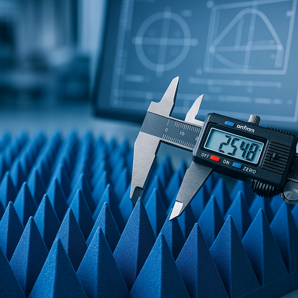
Pyramidal anechoic absorbers address this directly. Installed on the interior surfaces of a shielded room, their geometry progressively transitions wave impedance from free space to the absorbing material. This means incident energy is absorbed rather than reflected, across a broad frequency range.

The pyramidal shape isn't aesthetic – it's functional. The gradual taper minimizes the impedance discontinuity that causes reflection, and the increased surface area compared to flat material improves absorption efficiency. For facilities conducting testing to standards like MIL-STD-461, IEC 61000, or IEEE 1613, properly specified absorbers are not optional – they're part of what makes the test data valid.
Pro Tip: Commodity foam absorbers may meet spec at a narrow frequency range but fail outside it. For broadband EMP pulse testing environments, absorber selection should be based on measured attenuation data across the full test frequency range, not catalog descriptions.
Building a System That Actually Holds
The most common failure mode in real-world EM pulse protection installations isn't a single bad component – it's a gap in integration. An enclosure rated at 80 dB with an unfiltered power line defeats itself. Suppression components without proper grounding will fail at the moment of highest demand. A test chamber with commodity absorbers produces data that leads engineers toward false confidence in their hardened systems.
The layered model works when every layer is correctly specified, installed, and maintained:
- Structural shielding forms the outer barrier
- Penetration sealing maintains the barrier at every entry point
- Coordinated suppression protects conducted paths
- Grounding provides the energy dissipation pathway
- Redundancy and spare management ensure continuity if a layer is compromised
- Anechoic absorbers control the internal electromagnetic environment for testing and sensitive applications
Each layer depends on the others. Skipping one doesn't save cost – it typically nullifies the investment in the layers that remain.
Choosing the Right Absorber for Your Shielded Environment
If specifying a shielded test chamber, upgrading an existing EMC room, or validating a hardened facility against EMP pulse test protocols, the absorber specification deserves the same engineering rigor as every other component in the system.
dB Absorber supplies pyramidal anechoic absorbers engineered for broadband performance in demanding shielded room applications. Whether the requirement is standard commercial EMC testing or a high-attenuation military-grade test environment, the product range covers the frequency performance and physical configurations that serious EM pulse protection testing demands.
Frequently Asked Questions
What is the difference between an EMC shielded room and an EMP-hardened facility?
An EMC shielded room is typically designed to meet commercial electromagnetic compatibility testing standards, with moderate attenuation requirements. An EMP-hardened facility meets higher attenuation thresholds (often 80 dB or more per MIL-STD-188-125), with hardened penetrations, coordinated suppression on all entry points, and validated grounding systems.
Do anechoic absorbers themselves provide EM pulse protection?
No – anechoic absorbers control the internal electromagnetic environment inside a shielded room. They reduce reflections and standing waves, which is essential for accurate testing. The shielding itself is provided by the conductive enclosure.
Can standard surge protectors handle EMP pulse events?
Standard commercial surge protectors are designed for lightning-type transients and power line surges. They are not rated for the nanosecond-scale, high-frequency E1 phase of an EMP pulse. Specialized HEMP-rated filters and TVS diodes are required.
What standards govern military-grade EM shield performance?
The primary U.S. military standard for fixed facility shielding is MIL-STD-188-125. Equipment-level testing is governed by MIL-STD-461. Civilian and commercial equivalents include IEC 61000 series standards.
How often should EMP protection systems be tested?
Best practice in critical infrastructure is annual functional testing of shielding attenuation, with regular visual inspection of gaskets, bonding connections, and ground systems. Any modification to a shielded room – including cable additions – should trigger re-testing.