Conducted Immunity Test Procedures: A Step-by-Step Guide for EMC Engineers
Meta description: Learn how conducted immunity test procedures work with this step-by-step EMC guide. Understand equipment, setups, standards, and best practices for reliable compliance.
Conducted Immunity Test Procedures Explained: A Step-by-Step Guide for EMC Engineers
Engineers dealing with electronic products know that electromagnetic compatibility testing comes in two flavors. While emissions testing measures what leaks out of a device, conducted immunity testing flips the script entirely. This process examines how equipment handles electromagnetic disturbances traveling through physical connections like power cords and signal cables.
The testing world splits these disturbances into two categories. Continuous phenomena involve modulated waves applied over several minutes, while transient events pack concentrated energy into microsecond-long bursts. Understanding this difference helps determine which equipment to use and how long tests will take.
Why Regulatory Bodies Care About Conducted Immunity Testing
Markets across Europe, Australia, and dozens of other regions won't accept products without proper immunity verification. Medical devices, military equipment, and automotive systems face even stricter requirements. The IEC standards referenced by most international frameworks make conducted immunity testing mandatory, not optional.
Real-world environments throw constant interference at electronic devices. Power switching, nearby motors, and bundled cables create disturbances that can crash systems or corrupt data. Testing replicates these scenarios before customers experience failures.
Building Your Test System from Scratch
Setting up a proper conducted immunity test system requires more than plugging in a few instruments. Signal generators create the base waveforms, while RF power amplifiers boost them to test levels. The real magic happens with coupling devices that inject disturbances without frying equipment.
Core equipment needed:
- Signal generators covering the required frequency ranges
- Broadband RF power amplifiers
- Coupling decoupling networks (CDNs)
- Transient generators for burst and surge testing
- Automation software for test control
Coupling and decoupling networks deserve special attention. These devices present defined impedances while protecting auxiliary equipment from test signals. Choosing the wrong CDN can invalidate results or damage expensive power supplies.
Transient Generators Handle the Heavy Hitting
Transient testing needs specialized hardware. An electrical fast transient generator creates rapid pulse bursts, while surge generators deliver high-energy impulses mimicking lightning strikes. Each generator must meet strict waveform specifications down to nanosecond rise times.
Annual calibration through accredited labs keeps these instruments accurate. Standards like IEC 61000-4-2 and IEC 61000-4-4 specify tight tolerances on peak currents and pulse widths. Drift in these parameters compromises test validity.
Creating the Right Test Environment
The ground reference plane forms the foundation of any conducted immunity test setup. This conductive sheet—usually aluminum or copper—provides a stable reference and controls current paths. Size matters here, with standards specifying minimum clearances around equipment.
Connection quality between the plane and the facility ground can make or break test accuracy. Engineers should measure milliohms of resistance, not ohms. Poor grounding introduces measurement errors and creates safety hazards.
Where Equipment Goes and Why It Matters
Table-top equipment sits on insulating foam blocks above the ground plane. The spacing typically ranges from 0.8 to 1 meter, depending on the standard. This arrangement creates controlled coupling while maintaining safety distances.
Large industrial equipment that won't fit on tables needs modified setups. Standards provide alternative configurations that maintain test intent while acknowledging practical limits.
Running ESD Tests Without Damaging Anything
Electrostatic discharge testing simulates what happens when someone walks across carpet and touches equipment. Voltages can reach several kilovolts, discharging through devices in nanoseconds. The conducted immunity test for ESD uses specialized simulators with precise capacitance and resistance networks.
Contact discharge produces the most repeatable results. The simulator tip touches the equipment surface before triggering, creating consistent waveforms. Air discharge creates visible arcs but introduces more variability—use it only when surfaces are insulated.
Typical ESD test levels:
- Consumer products: 2-4 kV contact discharge
- Commercial equipment: 4 kV contact, 8 kV air
- Industrial devices: 6-8 kV contact discharge
- Critical systems: Up to 15 kV for specialized applications
Testing starts at lower voltages and ramps upward. Multiple discharges hit each test point while operators watch for malfunctions or damage.
Mastering Electrical Fast Transient Testing
Electrical fast transients mimic disturbances from relay switching, motor start-ups, and fluorescent lights. The waveform rises in about five nanoseconds with a 50-nanosecond duration—extremely quick but potentially destructive.
These pulses arrive in organized bursts rather than randomly. A typical sequence applies 75 pulses over 15 milliseconds, pauses, then repeats. This pattern continues for at least one minute per test level, stressing protection circuits.
Getting Signals Into Your Equipment
Power port testing uses direct injection through CDNs. Both line and neutral conductors receive disturbances while the protective earth stays clean. CDN ratings must match equipment power consumption, or damage occurs.
Signal ports get treated differently. Capacitive coupling clamps wrap around cable bundles, injecting transients without physical connections. Clamp placement follows strict rules—usually 0.1 meters from enclosures with specified cable routing.
Handling High-Energy Surge Tests Safely
Surge immunity addresses lightning-induced transients and switching overvoltages. The combination wave terminology refers to simultaneous voltage and current components: 1.2/50 microsecond voltage with 8/20 microsecond current. These longer events carry far more energy than fast transients.
Test levels depend on where the equipment is installed. Permanently wired devices face different exposures than plug-in products. Level 4 testing might apply 4 kV line-to-neutral or 8 kV line-to-earth, delivering hundreds of amperes instantly.
Protection components become critical during surge testing. Metal oxide varistors and transient voltage suppressors prevent damage, but they must be sized correctly. Starting with conservative levels verifies protection before applying maximum stress.
Navigating RF Conducted Immunity Challenges
Radio frequency conducted immunity testing evaluates how equipment handles electromagnetic fields coupling onto cables. The RF conducted immunity test system applies modulated RF signals from 150 kHz through 80 MHz, sometimes reaching 230 MHz.
The substitution method delivers accurate results. Calibration establishes signal levels needed for specified field strengths at injection points. Then, the equipment connects, and testing proceeds using stored calibration data.
Common injection methods:
- CDNs for power and I/O ports
- Electromagnetic clamps for cable bundles
- Bulk current injection probes for large installations
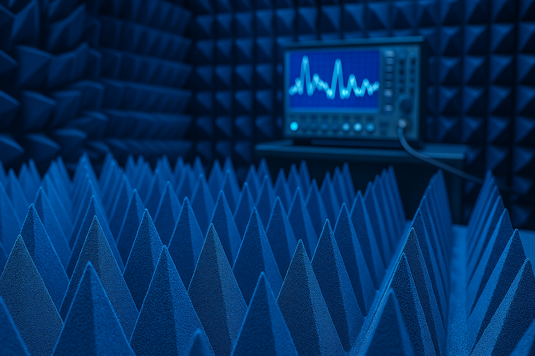
The 80% amplitude modulation at 1 kHz creates particularly challenging conditions. Equipment must maintain normal operation despite this interference. Testing facilities often use anechoic chambers lined with RF absorbers to create controlled electromagnetic environments and minimize unwanted reflections during testing.
Testing Equipment During Power Problems
Voltage dips and interruptions happen constantly in real power grids. Standards like IEC 61000-4-11 specify dip depths and durations that equipment must tolerate. Tests might include a 30% voltage reduction for 10 milliseconds or a complete interruption for 50 cycles.
Motor variacs combined with electronic switches handle single-phase testing. Three-phase requirements need programmable power sources that maintain phase relationships during transients.
What Counts as Passing?
Performance criteria define acceptable behavior during tests. Criterion A represents perfect operation with no degradation. Criterion B allows temporary glitches that self-correct. Criterion C permits operator intervention like power cycling. Criterion D means failure—permanent damage or inability to recover.
Safety-critical functions must meet Criterion A. Display flickering that instantly recovers might qualify as Criterion B. Equipment requiring a manual restart could satisfy Criterion C for non-critical features.
Cable Management Changes Everything
How cables get routed dramatically affects test outcomes. A 3-meter cable at 100 MHz acts like an efficient receiving antenna, coupling interference directly into equipment ports. Standards specify routing requirements because these details matter.
Distance from the ground plane, cable bundling, and shield termination all influence results. Test plans must document these parameters, and engineers must implement them consistently. Otherwise, the results become meaningless.
Fixing Problems Before They Become Failures
Reset events plague many products during testing. Transients glitch voltage regulators, causing brownout conditions. Adequate decoupling capacitance near sensitive ICs reduces this problem. Power supply rejection ratio matters too—good regulators maintain output despite input disturbances.
Communication interfaces fail when common-mode filtering proves inadequate. Differential signaling helps, but common-mode chokes with careful layout provide better protection. Analog circuits often need bandwidth limiting to prevent RF rectification, creating DC offsets.
Common failure modes to watch for:
- Equipment resets during transient tests
- Communication link dropouts
- Display corruption or flickering
- Memory errors or data loss
- Audible noise from speakers (1 kHz buzz)
Keeping Test Systems Accurate Over Time
Conducted immunity test system accuracy depends on regular calibration. Transient generators need annual calibration by accredited labs. Waveform parameters drift as components age, compromising test validity.
Coupling devices require verification, too. CDN insertion loss and return loss measurements ensure proper impedance matching. Degraded networks produce inaccurate levels even when generators work correctly.
Documentation supports reproducibility. Recording equipment serial numbers, calibration dates, and configurations enables meaningful retesting after design changes. Many testing facilities maintain rigorous testing processes to ensure consistency and accuracy across all measurements.
Making Testing More Efficient
Conducted immunity testing takes substantial time and resources. Smart planning maximizes value while minimizing costs. Preliminary checks using basic equipment catch obvious problems during development before expensive formal testing.
Automation transforms efficiency. Modern software handles frequency sweeps, level adjustments, and data logging automatically. Engineers can focus on analysis instead of babysitting instruments through lengthy sequences.
Wrapping Up the Process
Conducted immunity testing validates that the equipment survives real-world electromagnetic environments. Success requires understanding disturbance mechanisms, implementing proper protection, and running thorough tests. Products that pass these requirements deliver reliable performance instead of field failures.
The procedures outlined here provide a solid foundation for EMC engineering work. Standards evolve and equipment improves, but core principles stay constant. Products must withstand interference through physical connections, and testing proves this capability before customers encounter problems. Investing effort during design phases costs far less than fixing field failures after product release.
Looking for high-quality RF absorbers? Browse our in-stock pyramidal absorbers — shipping from California in 1-2 business days.