Automotive EMC Testing in Semi Anechoic Chambers: CISPR 25 Compliance Strategies
Meta description: Learn how to ensure CISPR 25 compliance with effective automotive EMC testing. Discover key strategies, materials, and setup tips for optimal results.
Automotive EMC Testing in Semi Anechoic Chamber: CISPR 25 Compliance Strategies That Work
Cars today pack more electronics than early spacecraft. Yet these systems must work together without creating electromagnetic chaos. When a navigation system interferes with engine control or radio signals disrupt safety sensors, lives hang in the balance.
The semi anechoic chamber stands as the ultimate testing ground for automotive electromagnetic compatibility. This specialized environment mimics real-world conditions while blocking external interference that could skew results.
Breaking Down the Semi Anechoic Chamber Mystery
Modern automotive EMC testing relies on precision environments that traditional labs cannot provide. External radio signals, cellular towers, and industrial equipment create electromagnetic noise that makes accurate measurements nearly impossible.
What Makes These Chambers Actually Work
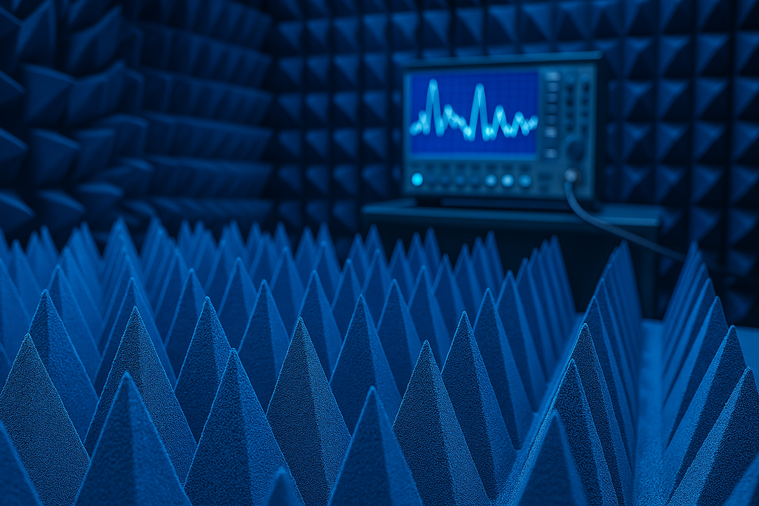
A semi anechoic chamber combines two opposing design philosophies. The walls and ceiling absorb electromagnetic waves like a sponge soaks up water. Meanwhile, the floor reflects signals just like roads, parking lots, and concrete surfaces do in real life.
This hybrid approach serves automotive testing better than fully anechoic chambers. Cars don't drive in electromagnetic voids. They operate above reflective surfaces that bounce radio waves in complex patterns.
The chamber's shielding system blocks outside interference completely. Thick metal walls create a Faraday cage effect that stops cellular signals, radio broadcasts, and WiFi networks from contaminating test data. Inside this controlled space, engineers can measure exactly what their automotive components actually emit.
Chamber Components That Matter Most
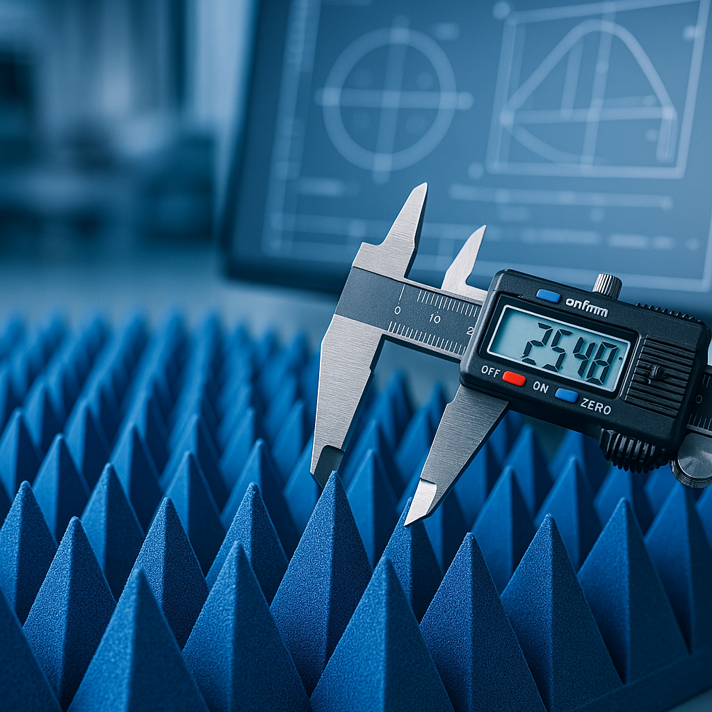
RF Absorbing Materials:
- Pyramidal foam structures convert electromagnetic energy to heat
- Carbon-loaded materials provide broadband absorption
- Ferrite tiles handle specific frequency ranges
- Hybrid absorbers combine multiple absorption mechanisms
The reflective ground plane requires special attention. Most chambers use galvanized steel sheets that provide consistent reflection characteristics across wide frequency ranges. This metallic surface must remain flat and continuous to avoid creating unwanted resonances or reflection patterns.
Chamber size determines which automotive systems can undergo testing. Smaller 3-meter chambers work well for individual components like radio modules or engine control units. Larger 10-meter facilities accommodate complete vehicle testing, though few companies require such extensive capabilities.
Why Traditional Testing Methods Fail
Standard laboratory environments introduce too many variables. Temperature fluctuations affect electronic performance. Humidity changes alter material properties. External electromagnetic interference creates measurement uncertainty that regulatory agencies won't accept.
The CISPR 16-1-4 standard specifies exact requirements for semi-anechoic chamber performance. These specifications exist because automotive manufacturers need consistent, repeatable test results regardless of geographic location or testing facility.
CISPR 25: The Automotive EMC Rulebook
Automotive electromagnetic compatibility testing follows strict protocols that have evolved over decades of industry experience. CISPR 25 represents the global consensus on how automotive electronics should behave in electromagnetic environments.
Setting Up the Perfect Test Environment
The semi anechoic chamber specification demands precise control over every environmental factor. Temperature must remain stable within narrow limits. Humidity levels require monitoring and adjustment. Even lighting systems need special consideration.
Critical Setup Elements:
- Grounded metal test table positioned exactly 1 meter from the measurement antennas
- Cable harnesses routed to match actual vehicle installations
- Power supplies that simulate real automotive electrical conditions
- Measurement equipment calibrated to traceable standards
Noiseless lighting presents an often-overlooked challenge. Standard fluorescent fixtures generate electromagnetic interference that can overwhelm sensitive emission measurements. LED systems require careful filtering to prevent switching noise from contaminating results.
The Device Under Test positioning affects measurement accuracy more than many engineers realize. Small changes in height, orientation, or proximity to other metal objects can shift emission patterns by several decibels.
Equipment Selection: Beyond Basic Specifications
Modern automotive components operate across frequency ranges that span seven decades—from 150 kHz audio circuits to 2.5 GHz wireless communication systems. No single measurement antenna covers this entire range effectively.
Essential Measurement Equipment:
- Spectrum analyzers with phase noise performance better than -130 dBc/Hz
- Logarithmic periodic antennas for 80 MHz to 2.5 GHz measurements
- Biconical antennas covering the 30 MHz to 300 MHz range
- Current probes calibrated for automotive harness geometries
Line Impedance Stabilization Networks deserve special attention in automotive applications. Unlike consumer electronics that operate from stable AC power, automotive systems must handle voltage variations from 9V to 16V, plus transient spikes reaching 100V or more.
The Art of Conducted Emission Testing
Conducted emissions travel along cables and wiring harnesses, eventually radiating as electromagnetic interference. The current probe method works best for automotive applications because it measures actual common-mode currents flowing in cable bundles.
Current probe placement requires a systematic methodology. Engineers must identify all cables connecting to the Device Under Test, then measure currents at standardized distances from the unit. The highest measured values determine compliance status.
Cable bundling practices significantly influence conducted emission measurements. Automotive harnesses contain mixed signal types—power cables carrying hundreds of amperes, control lines operating at microamp levels, and high-speed digital communications. Each cable type exhibits different electromagnetic characteristics.
Radiated Emission: The Real-World Challenge
Radiated emissions represent electromagnetic energy that escapes from automotive components and propagates through free space. These signals can interfere with radio reception, GPS navigation, cellular communications, and other vehicle systems.
The semi-anechoic chamber provides controlled conditions for radiated emission measurements. Antennas positioned at specific distances and heights capture electromagnetic fields while turntables rotate the Device Under Test through complete 360-degree cycles.
Measurement Methodology Steps:
1. Position DUT on the grounded turntable at the specified height
2. Configure the measurement antenna at the required distance and polarization
3. Rotate DUT in 10-degree increments while recording peak emissions
4. Repeat measurements with the antenna in vertical and horizontal polarizations
5. Document maximum emission levels across the complete frequency range
Peak detection requirements add complexity to radiated emission testing. CISPR 25 specifies different detector functions for various frequency ranges, reflecting the different interference mechanisms that affect automotive electronics.
Advanced Testing Strategies for Real-World Success
Successful automotive EMC testing extends beyond basic compliance measurements. Smart manufacturers use semi anechoic chamber capabilities to optimize designs, reduce costs, and accelerate development schedules.
Pre-Compliance Testing: The Smart Money Approach
Early-stage EMC evaluation saves both time and money. Design engineers can identify potential issues before expensive tooling commitments lock in problematic configurations.
Pre-compliance testing uses relaxed measurement procedures that provide quick feedback on design changes. Engineers can evaluate different shielding approaches, grounding schemes, and circuit modifications without formal test protocols.
The iterative nature of design optimization requires flexible test procedures. Unlike formal compliance testing, pre-compliance work allows engineers to focus on specific frequency ranges, component operating modes, or installation configurations that show problems.
Power Supply Realism: Beyond Simple DC Sources
Automotive electrical systems present harsh operating environments that desktop power supplies cannot replicate. Real vehicles subject electronic components to voltage variations, current surges, and transient spikes that dramatically affect electromagnetic behavior.
Battery simulation requires an understanding of automotive electrical system characteristics. SAE J1113 standards define specific test conditions that include alternator ripple, load dump transients, and cranking voltage variations.
Realistic Power Conditions:
- Nominal 12V operation with ±20% voltage tolerance
- Alternator ripple at 50Hz to 10kHz frequencies
- Load dump transients reaching 87V peak
- Cranking voltage drops to 6V for extended periods
These power supply variations affect both conducted and radiated emissions in ways that simple DC sources cannot reveal. Components may exhibit different electromagnetic signatures under stressed electrical conditions.
Component Operating Modes: The Hidden Variables
Modern automotive electronics operate across multiple functional states that each present different electromagnetic characteristics. Engine control units cycle through startup sequences, normal operation, diagnostic modes, and fault conditions.
Testing must evaluate all possible operating modes to identify worst-case emission scenarios. A radio module might meet limits during normal reception but fail compliance when switching between AM and FM bands.
Communication systems present particular challenges due to intermittent transmission patterns. Cellular modems, WiFi modules, and Bluetooth systems transmit data in bursts that create time-varying electromagnetic signatures. Standard measurement procedures must account for these operational variations.
Measurement Uncertainty: The Numbers Behind the Numbers
Every EMC measurement includes uncertainty that affects compliance decisions. The semi anechoic chamber environment contributes various uncertainty sources that testing engineers must understand and control.
Primary Uncertainty Sources:
- Antenna calibration accuracy (typically ±1.5 dB)
- Cable loss variations with temperature (±0.5 dB)
- Chamber reflection characteristics (±2.0 dB)
- Equipment drift during extended measurements (±0.3 dB)
Combined measurement uncertainty often reaches ±3 dB or more, representing a factor of two in actual emission levels. Products that barely pass compliance testing may fail when retested under slightly different conditions.
Regular validation measurements using calibrated signal sources help identify systematic errors in measurement procedures. These quality checks verify that chamber performance remains consistent over time and environmental conditions.
Making It All Work: Real Implementation Success
Successful automotive EMC testing requires attention to countless details that collectively determine measurement accuracy and regulatory acceptance. The semi anechoic chamber provides the foundation, but proper procedures and quality systems ensure reliable results.
Documentation requirements extend beyond simple measurement data. Regulatory agencies expect complete test reports that include equipment calibration records, environmental monitoring data, and detailed descriptions of test configurations.
Training requirements for EMC testing personnel continue growing as measurement procedures become more complex and regulatory standards evolve. Qualified technicians must understand both the technical aspects of electromagnetic measurements and the regulatory framework that governs automotive compliance.
The future of automotive EMC testing will demand greater measurement accuracy, broader frequency coverage, and faster test procedures. Semi anechoic chamber capabilities must evolve to meet these challenges while maintaining the measurement repeatability that makes regulatory compliance possible.
Looking for high-quality RF absorbers? Browse our in-stock pyramidal absorbers — shipping from California in 1-2 business days.