RF Testing Compliance: The Complete Guide to Successful Product Launches
Meta description: Master RF testing compliance to ensure your wireless device meets standards, avoids penalties, and achieves success. Learn materials, testing, and strategies.
The Complete Guide to RF Testing Compliance: EMC Standards That Could Make or Break Your Product Launch
Product failures cost companies millions. RF testing compliance stands as the final barrier between wireless devices and market success. One failed test can delay launches by months, destroy budgets, and hand competitors the advantage.
Wireless products face stricter scrutiny than ever before. Regulatory bodies worldwide have tightened electromagnetic compatibility standards. The radio spectrum grows more crowded each year, making interference prevention critical.
Why RF Testing Determines Market Success
Electromagnetic interference affects everything from hospital equipment to aircraft navigation systems. Regulators take this seriously. Non-compliant devices face immediate market withdrawal and hefty fines.
The FCC alone issued over $200 million in penalties for equipment violations in recent years. European authorities have similar enforcement power under the RED regulations. These aren't empty threats - major manufacturers regularly face compliance actions.
The High Stakes Game of Spectrum Management
Radio frequency test protocols serve multiple purposes beyond basic compliance. They protect critical infrastructure, ensure public safety, and maintain spectrum efficiency. Emergency services, military communications, and scientific research all depend on clean electromagnetic environments.
Modern cities contain thousands of wireless devices per square kilometer. Each device must coexist without causing harmful interference. RF testing verifies this compatibility through rigorous measurement protocols.
Think about smartphone usage in dense urban areas. Without proper RF testing, dropped calls and data failures would plague every network. The seamless connectivity users expect requires strict adherence to power limits and frequency stability requirements.
Market Access Roadblocks
Different regions maintain distinct regulatory frameworks:
- United States: FCC Part 15 rules govern most wireless devices
- European Union: RED 2014/53/EU covers radio equipment certification
- Canada: ISED regulations mirror FCC requirements with regional variations
- Japan: MIC certification processes emphasize interference prevention
- Australia: ACMA standards focus on spectrum protection
Each market requires separate testing and documentation. Global product launches demand comprehensive compliance strategies covering multiple regulatory zones simultaneously.
Technical Requirements That Trip Up Products
RF testing encompasses far more than simple power measurements. Modern wireless devices must demonstrate performance across multiple technical domains while maintaining compliance under varying conditions.
Power Performance Under the Microscope
Conducted power measurements form the foundation of all RF testing protocols. Devices must maintain specified power levels across temperature ranges, supply voltages, and component tolerances. This sounds straightforward until engineers discover how many factors affect power output.
Temperature coefficients in RF components cause power drift. Crystal oscillators shift frequency with thermal changes. Amplifier gain varies with supply voltage fluctuations. These interactions create complex compliance challenges.
Battery-powered devices present additional complications. Power output often changes significantly as battery voltage drops from 4.2V to 3.0V. Many products pass testing with fresh batteries but fail compliance near end-of-life conditions.
Frequency Stability Challenges Nobody Talks About
Frequency accuracy requirements have tightened dramatically. Wi-Fi devices must maintain ±20 ppm accuracy across operating conditions. Bluetooth Low Energy demands even stricter tolerances for reliable connections.
Crystal aging affects long-term stability. Manufacturing tolerances create unit-to-unit variations. Temperature cycling reveals thermal hysteresis effects in timing components. These factors compound to create frequency stability challenges.
Load pulling from antenna mismatches can shift oscillator frequency. Poor PCB layout introduces unwanted coupling. Component placement near heat sources causes thermal gradients. Each factor requires careful attention during the design and testing phases.
Spurious Emissions: The Hidden Killers
Harmonic content analysis extends well beyond fundamental frequencies. Second and third harmonics often fall within sensitive frequency bands used by other services. GPS receivers, for example, operate near common Wi-Fi harmonic frequencies.
Intermodulation products from nonlinear circuits create additional spurious signals. Two-tone testing reveals these unwanted mixing products. Poor amplifier linearity or inadequate filtering can cause significant compliance failures.
Digital switching noise from microprocessors often appears as broadband emissions. Clock harmonics spread across wide frequency ranges. Proper PCB design and filtering become critical for compliance success.
Pre-Compliance Testing: Your Safety Net
Smart companies invest in pre-compliance testing capabilities. Basic equipment purchases pay for themselves by catching problems early. Spectrum analyzers, power meters, and near-field probes form the minimum test setup.
Early testing identifies design problems when fixes cost hundreds instead of thousands. Component selection mistakes become obvious through simple measurements. Layout issues reveal themselves through emission scanning techniques.
Building Your Test Arsenal
Essential pre-compliance equipment includes:
- Spectrum analyzer: 9 kHz to 6 GHz, minimum range for most applications
- Power meter: Calibrated sensors for accurate conducted measurements
- Near-field probes: H-field and E-field probes for emission source identification
- Vector network analyzer: Return loss and filter response verification
Test setup quality affects measurement accuracy significantly. Proper grounding, cable management, and ambient noise control ensure repeatable results. Investment in quality test fixtures and adapters reduces measurement uncertainty.
Temperature chambers enable environmental testing during development. Supply voltage variation testing requires programmable power supplies. Multiple device samples help identify unit-to-unit performance variations early in the process.
Measurement Techniques That Matter
Conducted power verification should occur first in any test sequence. This baseline measurement confirms proper device operation before proceeding to emission testing. Power stability across temperature and voltage variations reveals potential compliance risks.
Return loss measurements identify antenna matching problems that could affect radiated performance. Poor antenna efficiency wastes power and may cause compliance margin issues. VSWR measurements help optimize antenna designs for maximum power transfer.
Emission prescanning using wide bandwidth settings provides quick identification of potential spurious signals. Narrowband analysis of suspicious frequencies determines actual emission levels. Time-domain gating helps separate device emissions from ambient interference.
Working with Certification Labs: Success Strategies
Test lab selection requires careful evaluation of capabilities and experience. Accreditation scope must cover target markets and product categories. Equipment specifications should meet or exceed testing requirements for frequency range and measurement accuracy.
Turnaround time becomes critical for product launch schedules. Popular labs often book weeks or months in advance. Planning certification testing early prevents schedule delays and rushed decisions.
Documentation Excellence
Complete technical documentation streamlines certification processes. Test labs require detailed product information before testing begins:
1. Circuit schematics showing RF signal paths and filtering
2. PCB layout files highlighting sensitive areas and component placement
3. Block diagrams explaining system architecture and signal flow
4. User manuals describing normal operation modes
5. Test mode descriptions enabling required measurements
Incomplete documentation causes delays and additional charges. Clear labeling and organization help lab technicians work efficiently. Electronic file formats should be current and compatible with lab systems.
Sample preparation includes mechanical considerations beyond electrical requirements. Test fixtures may be needed for unusual form factors. Multiple samples provide backup units if problems occur during testing.
Test Lab Communication Protocol
Establishing clear communication channels prevents misunderstandings and delays. Designated technical contacts should have the authority to make testing decisions. Regular status updates help track progress and identify potential issues early.
Pre-test meetings allow discussion of specific requirements and test procedures. Lab engineers can suggest optimizations based on experience with similar products. These conversations often prevent problems before they occur.
Remote monitoring capabilities let development teams observe testing progress. Real-time data access enables quick decisions when issues arise. This visibility reduces the need for multiple test iterations.
Module Integration: Shortcuts with Strings Attached
Pre-certified modules offer attractive alternatives to custom RF designs. Reduced testing scope and faster time-to-market make modules appealing for many applications. However, certification benefits come with strict integration requirements.
Reference design compliance becomes mandatory for maintaining module certifications. Antenna placement, ground plane size, and component clearances must match specifications exactly. Minor deviations can invalidate certifications completely.
Integration Compliance Checklist
Module integration requires attention to multiple technical details:
- Antenna position within specified tolerances
- Ground plane dimensions matching reference design
- Component clearances around RF sections
- Shield grounding and material specifications
- Cable routing following prescribed paths
Documentation requirements increase significantly when using pre-certified modules. Integration statements must confirm compliance with original certification conditions. Photographs showing the final implementation help demonstrate proper installation.
Antenna selection often limits design flexibility. Module certifications typically cover specific antenna models and placements. Custom antenna designs may require full device certification even when using pre-certified modules.
When Module Benefits Disappear
Certain modifications automatically trigger full certification requirements. Antenna changes, shield modifications, or PCB layout alterations can void module certifications. Understanding these limitations prevents costly surprises during compliance testing.
Software modifications affecting RF performance also impact certification status. Power level changes, modulation parameters, or frequency band additions require recertification. Even seemingly minor firmware updates can have compliance implications.
Multiple module installations in a single product create additional complexity. Coexistence testing becomes necessary to verify proper operation without mutual interference. This testing often requires custom procedures beyond standard certification protocols.
The Bottom Line
RF testing compliance shapes product success more than most engineers realize. Technical excellence means nothing without market access. Regulatory compliance opens doors while failures slam them shut.
Smart companies treat RF testing as integral to design processes rather than final hurdles. Early planning, systematic testing, and professional execution create competitive advantages. The investment in proper compliance processes pays dividends through successful product launches and avoided penalties.
The wireless industry continues evolving rapidly. New technologies, changing regulations, and increasing spectrum congestion make RF testing expertise more valuable than ever. Companies that master these challenges will dominate future markets while others struggle with compliance failures and delayed launches.
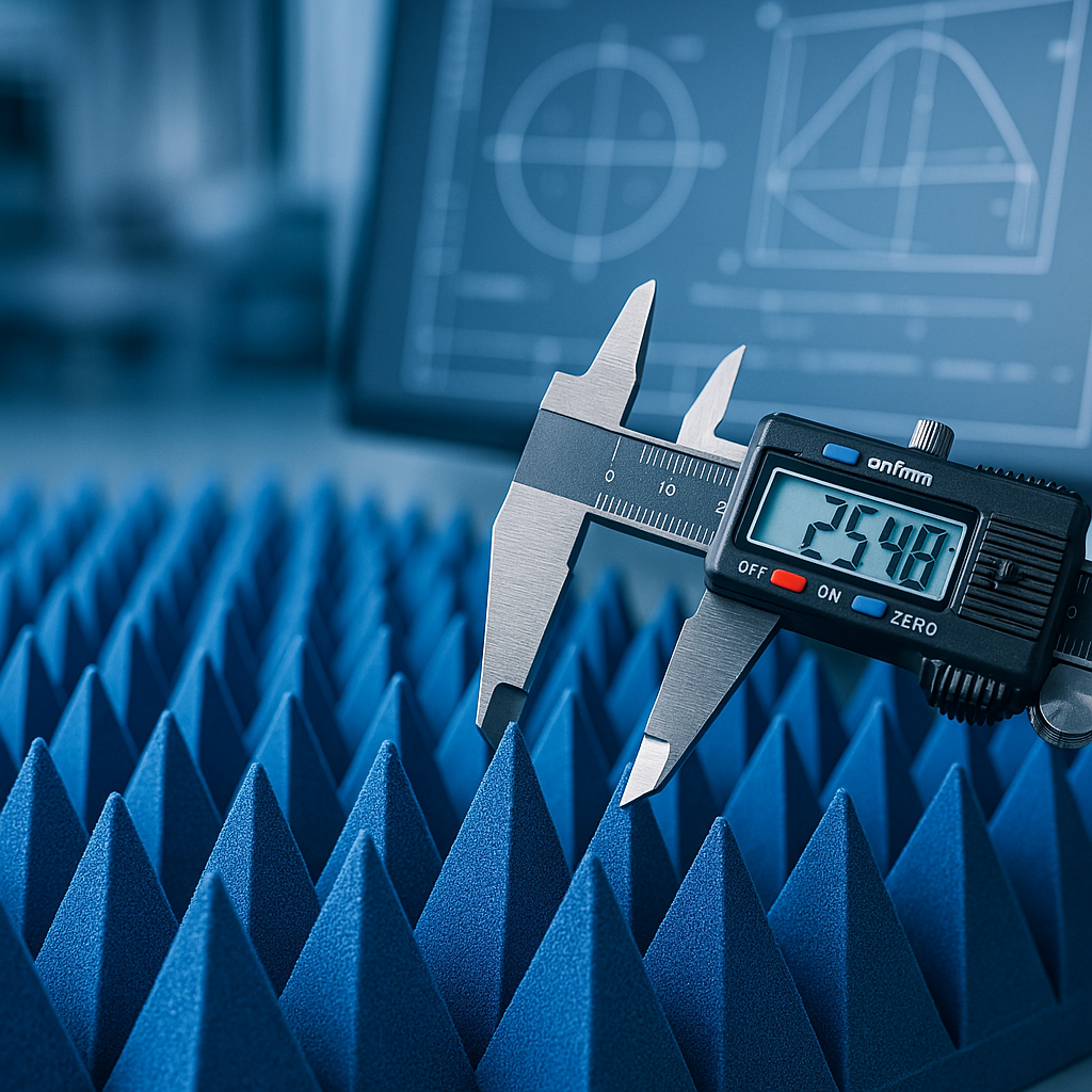
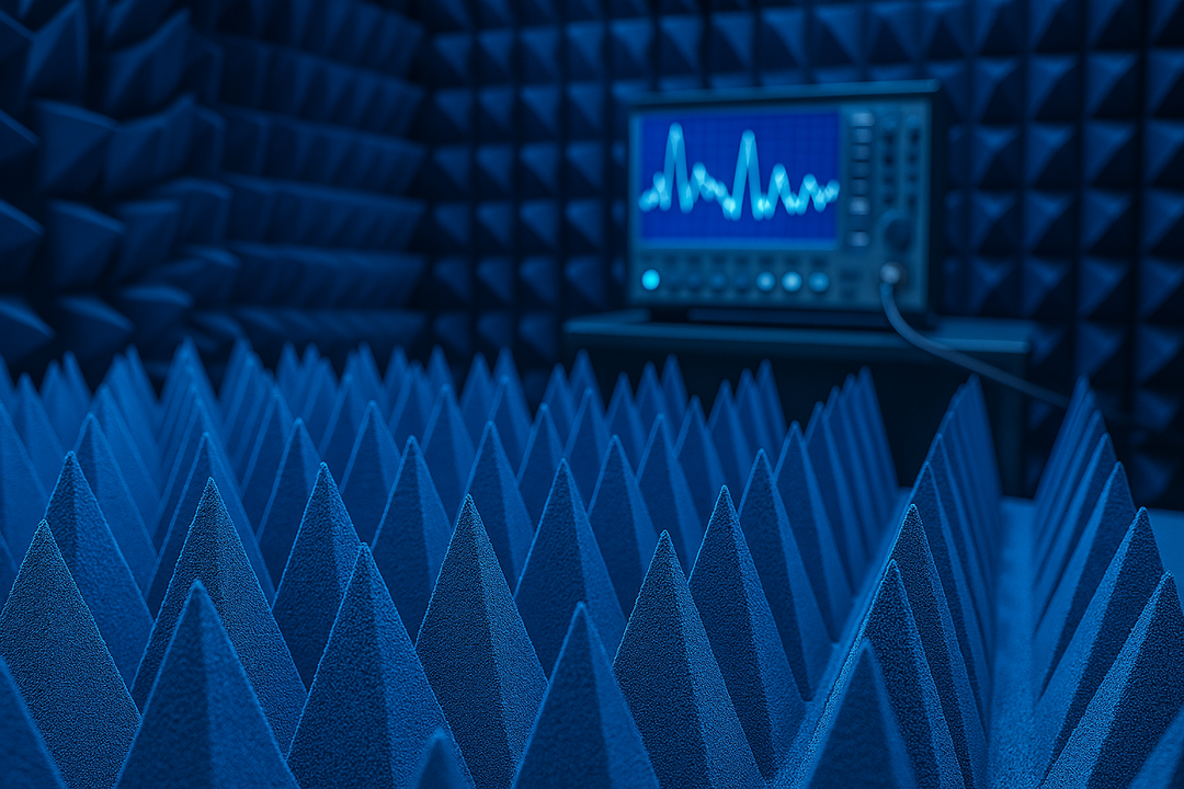
Looking for high-quality RF absorbers? Browse our in-stock pyramidal absorbers — shipping from California in 1-2 business days.