Setting Up Your First Over-the-Air Testing Environment
Meta description: Learn how to set up your first over-the-air testing environment with the right equipment, chamber design, and best practices to ensure accurate wireless device testing.
Setting Up Your First Over-the-Air Testing Environment: Equipment, Chamber Design, and Best Practices
Wireless technology runs nearly everything these days—from smartphones to smart homes. Testing how well these devices actually perform in real-world conditions isn't just a nice-to-have anymore. Over-the-air testing gives engineers the complex data they need to confirm their products work properly before shipping them to customers.
Setting up a testing environment isn't as simple as buying equipment and flipping a switch. The process requires understanding how specialized instruments, carefully designed spaces, and proven methods work together. Getting the setup right from the start saves money and prevents headaches later.
What Makes Over-the-Air Testing Different
Over-the-air testing measures how wireless devices send and receive radio signals under conditions that mirror actual use. Unlike traditional testing that plugs directly into a device's ports, over-the-air antenna testing evaluates the complete package—antenna, housing, and anything else that might affect signal strength. This method catches problems that lab bench testing misses entirely.
The tricky part? Creating an environment where measurements stay consistent. Wi-Fi routers, cell towers, and even kitchen appliances can mess with test data. Reflections bouncing around inside the test space create interference patterns that throw off readings. Controlling these issues takes specialized infrastructure.
The Equipment You'll Actually Need
Building a functional testing setup requires several key components working in harmony.
Tools for Signal Work
The main instruments handle signal generation and analysis. Vector network analyzers work well for passive antenna measurements, scanning through frequencies while tracking how signals reflect and transmit. For active devices like phones or wireless modules, radio communication testers provide protocol emulation and deeper analysis capabilities.
Popular models include:
- Rohde & Schwarz CMW500
- Anritsu MT8000A
- Keysight EXA Signal Analyzer
These instruments carry hefty price tags. Choosing the right one depends entirely on which wireless technologies need testing. Bluetooth testing requires different features than 5G antenna certification.
Building the Protected Space
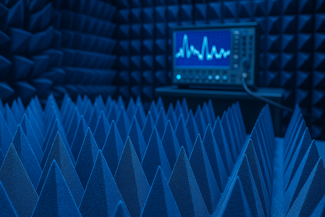
RF anechoic chambers create a controlled environment where measurements happen. Metal walls block outside interference while pyramid-shaped foam absorbers on interior surfaces soak up reflections. The foam contains conductive materials that turn electromagnetic energy into heat across specific frequency ranges.
Smaller operations might use compact shielded boxes, while larger facilities need walk-in chambers big enough for cars or aircraft components. Size requirements connect directly to measurement distances and frequency bands.
Positioning and Measurement Hardware
Probe antennas send signals to test devices and capture their responses. Horn antennas handle higher frequencies well, while Vivaldi antennas cover multiple bands. The specific choice depends on frequency range and measurement goals.
Positioning systems provide the mechanical framework for rotating devices or antennas through various orientations. Most systems combine a turntable for horizontal rotation with an arm or gimbal for vertical adjustments. This three-dimensional movement maps out complete radiation patterns.
Component
Purpose
Typical Options
Signal Generator
Creates test signals
VNA, Communication Tester
Chamber
Blocks interference
Anechoic, Shielded Box
Probe Antenna
Sends/receives signals
Horn, Vivaldi, Dipole
Positioner
Rotates device/antenna
Turntable + Gimbal
Control System
Automates testing
MVG WaveStudio, MilliBox
The Supporting Cast
High-quality RF cables maintain clean signals between instruments and antennas. Low-noise preamplifiers boost weak signals above background noise. Filters strip out unwanted frequencies that could confuse measurements. These components might seem secondary, but cheap cables or excessive signal loss can ruin even the best primary equipment.
Computer control systems coordinate everything through automation. Software packages handle test configuration, positioning control, and result analysis. Automation becomes critical when testing involves hundreds or thousands of measurement points.
Getting the Chamber Design Right
Space Planning That Works
Chamber size ranks among the most important design choices. The distance between the probe antenna and the test device must meet far-field requirements for accurate pattern measurements. This distance scales with both frequency and device size.
A standard guideline suggests maintaining a 1:3 ratio between product volume and chamber working volume. Undersized chambers force near-field measurements that don't represent real-world performance. Oversized chambers just waste money.
Temperature control matters too. Over-the-air test chambers generate heat from absorbers, electronics, and test devices. Leaving three feet of clearance around chamber walls allows airflow and maintenance access.
Choosing Absorber Materials
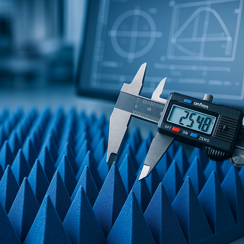
Absorber materials lining the walls determine how well the space kills reflections. Pyramidal foam absorbers remain the standard choice. Their pyramid shape creates gradual transitions that minimize reflections across wide frequency ranges.
Quality absorbers achieve coefficients above 0.99 for target frequency ranges. Lower-grade options might work for narrow applications, but broadband testing demands premium materials. Absorber thickness increases at lower frequencies since longer wavelengths need more material depth.
Shielding the Space
The outer chamber structure must block external signals from sneaking in. Metal walls, doors, and entry points create an electromagnetic barrier. Door seals and filtered power connections prevent leakage.
Testing near cell towers or radio stations demands stronger shielding than in quiet locations. Checking the electromagnetic environment beforehand helps determine adequate protection levels.
Smart Practices for Better Results
Define Goals Before Buying
What performance numbers actually matter? Total radiated power and total isotropic sensitivity are common metrics, but gain patterns, polarization, and efficiency might also be relevant. Nailing down objectives before shopping prevents expensive mistakes.
Key questions to answer:
- Which wireless protocols need testing?
- What frequency bands matter?
- Which device types will be tested?
- What certification standards apply?
Set Your Baseline
Measure the empty chamber before testing devices. These baseline readings reveal background signals and system quirks that might affect results later. Knowing the noise floor determines the weakest signals measurable.
Path loss measurements with reference antennas provide system verification. Comparing measured losses against calculations confirms that the chamber and positioning system work correctly.
Keep Things Consistent
Loading test devices in identical positions for repeated measurements keeps data comparable. Small position changes significantly alter measured patterns, especially at higher frequencies. Documenting mounting methods and reference points lets others replicate results.
Consistency extends to cable routing and instrument settings. Changes between measurements introduce variables that complicate interpretation.
Automate the Repetitive Stuff
Manual measurements get tedious when mapping patterns across hundreds of positions. Automated sequences improve efficiency while cutting human error. Control software steps through test matrices, adjusting positions and recording data without operator involvement.
Automation also boosts repeatability by executing tests identically every time. Random human variations disappear when computers handle the work.
Maintain and Calibrate Regularly
Over-the-air testing systems need ongoing attention. Annual calibrations verify instruments still meet specs. RF cables develop issues from repeated bending and connector wear. Absorber materials get damaged or contaminated, hurting chamber performance.
Maintenance schedules based on manufacturer recommendations prevent failures during critical testing. Tracking calibration dates and maintenance work provides documentation for quality systems.
Stick to Industry Standards
Organizations like CTIA and 3GPP publish standardized test methods for over-the-air antenna testing. Following established procedures ensures customers, regulators, and certification bodies recognize results. Standards specify measurement distances, positioning sequences, and reporting formats.
Custom methods work fine for internal development, but straying from standards creates problems when seeking external validation or regulatory approval.
Wrapping Up
Creating an effective over-the-air testing environment takes real investment in equipment, space, and knowledge. The complexity might seem daunting initially, but tackling the project in phases makes it manageable. Clear requirements, appropriate equipment selection, thoughtful chamber design, and disciplined procedures build the foundation for reliable wireless device testing.
The upfront effort pays off through years of productive work. As wireless technologies push toward higher frequencies and more complex systems, having solid over-the-air testing capabilities becomes increasingly valuable. Organizations investing in proper infrastructure now can characterize next-generation devices as they appear.
Whether validating advanced 5G implementations or checking basic IoT sensor performance, over-the-air testing provides the proof needed to ship products confidently. Specialized equipment, properly designed chambers, and disciplined methodology transform engineering specifications into verified product performance.
Looking for high-quality RF absorbers? Browse our in-stock pyramidal absorbers — shipping from California in 1-2 business days.